Dark Activated Switch Circuits
Wednesday, June 12, 2013
3 Wire Serial LCD Circuits using a Shift Register
74HC595 is a high-speed 8-bit serial in, serial or parallel-out shift register with a storage register and 3-state outputs.
The shift register and storage registers have separate clocks, SH_CP and ST_CP respectively. Data in the shift register is shifted on the positive-going transitions of SH_CP, and the content of shift register will be transferred to the storage register on a positive-going transition of the ST_CP. If we tie both the clocks together, the shift register will always be one clock ahead of the storage register. The 8-bit data of the storage register will appear at the parallel output (Q0-Q7) when the output enable (OE) is low.
In this project, SH_CP and ST_CP are tied together. So, if we want to receive a serially transferred 8-bit into parallel form at Q0-Q7, an extra clock pulse is required after transmitting the 8-th bit of serial data because the clocks are tied and the storage register is 1-clock behind the shift register.
HD44780-based character LCD
Providing detail explanation of individual LCD pin doesnt fall within the scope of this project. If you are a beginner with LCD, I recommend to read these two articles first from Everyday Practical Electronics magazine : How to use intelligent LCDs
The SH_CP (11) and ST_CP (12) clock inputs of 75HC595 are tied together, and will be driven by one microcontroller pin. Serial data from microcontroller is fed to the shift register through DS (14) pin. OE (13) pin is grounded and reset pin MR (10) is pulled high. Parallel outputs Q0-Q3 from 74HC595 are connected to D4-D7 pins of the LCD module. Similarly, Q4 output serves for RS control pin. If the LCD module comes with a built-in backlight LED, it can simply be turned ON or OFF through LED control pin shown above. Pulling the LED pin to logic high will turn the back light ON.
Software
A first, a bit of data fed to DS pin of 74HC595 appears at Q0 output after 2 clocks (because SH_CP and ST_CP are tied). So, sending 4-bit data (D4-D7) and an RS signal require 6 clock pulses till they appear at Q0-Q4 outputs respectively. When the LCD module is turned ON, it is initialized in 8-bit mode. A number of initializing commands should be sent to operate the LCD module in 4-bit mode. All the driver routines that are discussed here are written in mikroC compiler. They work only for a 16x2 LCD module. User can modify the initialization operations inside the Initialize_LCD() routine to account for other LCD configurations. The driver routines and their functions are described below.
- Initialize_LCD() : It initializes the LCD module to operate into 4-bit mode, 2 lines display, 5x7 size character, display ON, and no cursor.
- Write_LCD_Data() : Sends a character byte to display at current cursor position.
- Write_LCD_Cmd() : Write a command byte to the LCD module.
- Write_LCD_Nibble() : Data or command byte is sent to the LCD module as two nibbles. So this function routine takes care for sending the nibble data to the LCD module.
- Write_LCD_Text() : This routine is for sending a character string to display at current cursor position.
- Position_LCD() : To change the current cursor position
At the beginning of your program, you need to define Data_Pin, Clk_Pin, and Enable_Pin to the chosen microcontroller ports. I am going to demonstrate here how to use these driver routines to display two blinking character strings, Message1 and Message2, at different locations. I am going to test our serial LCD module with PIC12F683 microcontroller. The test circuit is shown below.
Note: My PIC12F683 Settings
Running at 4 MHz internal clock, MCLR disabled, WDT OFF.
Clock, Data, and Enable lines are served through GP1, GP5, and GP2 ports.
/* 3-wire Serial LCD using 74HC595
Rajendra Bhatt, Sep 6, 2010
*/
sbit Data_Pin at GP5_bit;
sbit Clk_Pin at GP1_bit;
sbit Enable_Pin at GP2_bit;
// Always mention this definition statement
unsigned short Low_Nibble, High_Nibble, p, q, Mask, N,t, RS, Flag, temp;
void Delay_50ms(){
Delay_ms(50);
}
void Write_LCD_Nibble(unsigned short N){
Enable_Pin = 0;
// ****** Write RS *********
Clk_Pin = 0;
Data_Pin = RS;
Clk_Pin = 1;
Clk_Pin = 0;
// ****** End RS Write
// Shift in 4 bits
Mask = 8;
for (t=0; t<4; t++){
Flag = N & Mask;
if(Flag==0) Data_Pin = 0;
else Data_Pin = 1;
Clk_Pin = 1;
Clk_Pin = 0;
Mask = Mask >> 1;
}
// One more clock because SC and ST clks are tied
Clk_Pin = 1;
Clk_Pin = 0;
Data_Pin = 0;
Enable_Pin = 1;
Enable_Pin = 0;
}
// ******* Write Nibble Ends
void Write_LCD_Data(unsigned short D){
RS = 1; // It is Data, not command
Low_Nibble = D & 15;
High_Nibble = D/16;
Write_LCD_Nibble(High_Nibble);
Write_LCD_Nibble(Low_Nibble);
}
void Write_LCD_Cmd(unsigned short C){
RS = 0; // It is command, not data
Low_Nibble = C & 15;
High_Nibble = C/16;
Write_LCD_Nibble(High_Nibble);
Write_LCD_Nibble(Low_Nibble);
}
void Initialize_LCD(){
Delay_50ms();
Write_LCD_Cmd(0x20); // Wake-Up Sequence
Delay_50ms();
Write_LCD_Cmd(0x20);
Delay_50ms();
Write_LCD_Cmd(0x20);
Delay_50ms();
Write_LCD_Cmd(0x28); // 4-bits, 2 lines, 5x7 font
Delay_50ms();
Write_LCD_Cmd(0x0C); // Display ON, No cursors
Delay_50ms();
Write_LCD_Cmd(0x06); // Entry mode- Auto-increment, No Display shifting
Delay_50ms();
Write_LCD_Cmd(0x01);
Delay_50ms();
}
void Position_LCD(unsigned short x, unsigned short y){
temp = 127 + y;
if (x == 2) temp = temp + 64;
Write_LCD_Cmd(temp);
}
void Write_LCD_Text(char *StrData){
q = strlen(StrData);
for (p = 0; p temp = StrData[p];
Write_LCD_Data(temp);
}
}
char Message1[] = "3-Wire LCD";
char Message2[] = "using 74HC595";
void main() {
CMCON0 = 7; // Disable Comparators
TRISIO = 0b00001000; // All Outputs except GP3
ANSEL = 0x00; // No analog i/p
Initialize_LCD();
do {
Position_LCD(1,4);
Write_LCD_Text(Message1);
Position_LCD(2,2);
Write_LCD_Text(Message2);
Delay_ms(1500);
Write_LCD_Cmd(0x01); // Clear LCD
delay_ms(1000);
} while(1);
}
LED Light Bulbs Save Energy on Mysore Palace Board
As the first step towards the conservation of energy, The Mysore Palace Board began working with the replacement of equipment outside the halls of the palace (along the tracks and walk to the door) with Eco-LED (light emitting diode of light). 12 volt led lights will be enough.
As part of the first stage of labor, 685 units were replaced with LED lights to a golden color, as desired by the Council of the palace.
The contract was awarded to a man named S. Mysore Nagaraj, CEO of green light Trishul, Bangalore.
Star of Mysore Nagaraj said the Rs 77 lakh contract for the replacement of more than 3,000 lights on the Palace Square, which will be implemented in five phases. "Each LED unit is guaranteed for 50,000 hours," said Nagaraj and added, "the unit cost of Rs 30 watts. 14 000 and 60 watt unit cost of Rs 28000th service and replacement guarantee has been issued for five years. "
Nagaraj said the LED lights with LED other contractors that submitted bids were reviewed by representatives of the Board of Directors of NIE engineers and technicians Palace before awarding the contract. They insisted on using a light outside the Palace of Golden Hue.
".. The main advantage of energy saving LED lamps produce more light on the production of electricity used for LED bulbs are a great power, consumes less electricity," said Nagaraj, adding LED lights have the stabilizer circuit voltage , which takes the voltage range of 90 to 270 volts. They are also recyclable, he said.
Related items:12 volt led light bulbs.12 volt led light bulb
Wednesday, June 5, 2013
Damaging Effects Electropollution
The Damaging Effects Of Electropollution.
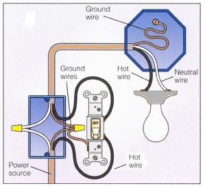
Basic 2 Way Switch Wiring Diagram.
How To Install Electrical Wiring Doityourself Com.
Here Iswhat The Electrical Wiring Would Look Like For This Situation.
Gfci Outlet Wiring Diagram Pdf 55kb.
Basic Electrical Connections.
Basic Electrical Wiring Basic Electrical Wiring Project Beginner.
Chapter 2 Automotive Electrical Circuits And Wiring.
Heres A Diagram I Found I Dont Know If Its Helpful Or Not.
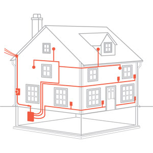
Or Residential Home With Basic Electrical Wiring And Hvac Complete.
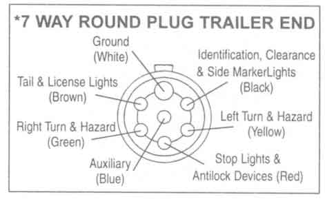
Trailer Wiring Diagram
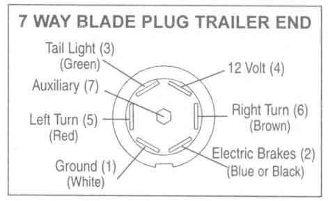
Http Www Easternmarine Com 7 Pole Rv Blade Trailer End Plug 6 Cable.
Trailer Wiring Diagram.
Woodalls Open Roads Forum Class C Motorhomes Towed Vehicle Battery.
Trailer Wiring Problem Dodge Diesel Diesel Truck Resource Forums.
79088 Trailer Lights Wiring Harness Trailer Wiring Bmp.
Trailer Light Wiring Typical Trailer Light Wiring Diagram.
Trailer Wiring Diagram Jpg.
Axle Trailer Axles And Running Gear Components Trailer Plug Wiring.
Wiringdiagrams21 Com 2010 06 20 Typical 7 Way Trailer Wiring Diagram.
Wiring Diagram For Trailers.
Ethernet Cableskarl Shoemakerak2o
Wiring Diagram.
How To Make A Rj45 Cable Tester.
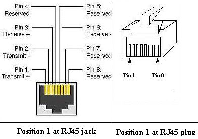
Welcome To Tutor Piggy Blogspot Com Rj45 Wiring Diagram.
The Exact Sequence Represented In The Wiring Diagram Labeled 568b.
Peak Electronic Design Limited Ethernet Wiring Diagrams Patch.
Rj45 To Db9 Link Adapter.
Rj45 Wiring.
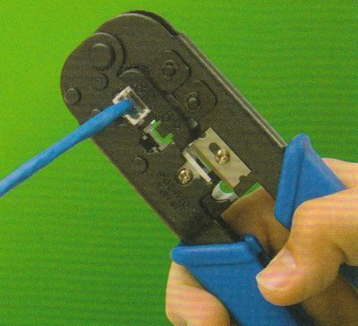
Crimp Rj45.
One At The Good Old Home Depot See Here Rj6 Rj45 Crimp Tool.
Ethernet Cables By Karl Shoemaker Ak2o.
Tuesday, June 4, 2013
Volkswagen Cabriolet Cruise Control Wiring Schematic Thumb
Suzuki Gsx R1100 Charging System Diagram 94 96 Circuit Schematic.
Generator Components Get Domain Pictures Getdomainvids Com.
Information About 1997 Honda Civic Ex Charging System Wiring Diagram.
Volkswagen Cabriolet Cruise Control Wiring Schematic Thumb Png.
Generator Internal Circuit Jpg.
Briggs And Straton Carburetor Diagram Toefl.
Parking Light 4 Right Headlight 5 Negative Ground Cable 6 Generator.
Land Rover 300tdi Cylinder Block Piston Camshaft Diesel Engine Diagram.
Find More Information About 1947 Harley Davidson Wiring Diagram Here.
Hot Hot Neutral Carry The Current To The Generator S Distribution.
Productsdelfingen Industry
Gm Tpi Products Wiring Harnesses Tpi Harness 1986 89 Corvette.
Other Products Delfingen Industry.
Hydrox Mobile Rus Products Vehicle Wiring Diagram.
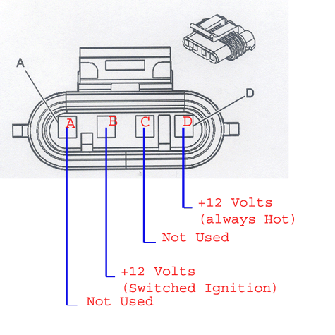
Wiring Connections For Gm Serpentine Kit Alternators.
Split Charge Electrical Wiring Diagram.
Our Products Wiring Diagram 1970 76 Tecumseh Powered.
Products Accessory Equipment Light Vehicle Wiring Kit Roll Bar.
System Wiring Diagrams.
Vehicle Wiring Kit.
Related Products.
Subscribe to:
Posts (Atom)