Friday, December 27, 2013

The main body of cell phone jammer should be installed on the top

 Personality, social factors and individual background variables on the mobile phone text messages have a certain psychological predictors. Personality, social factors and individual psychological background variables through SMS mobile phone text messages as an intermediary variables on the use of the Indirect impact. While the extraversion personality and sense of responsibility can also be used directly to predict behavior of mobile phone text messages.  Study were 475 valid questionnaires, which have cell phones, the number of people using SMS 81.5%. And consistent with previous findings, gender, whether to use SMS, SMS cost ratio and the number of SMS sent in did not show significant differences in the impact of family origin is an important factor in the use of SMS. To the individual background variables, social factors and Big Five personality as a predictor variable, the need to make friends as the dependent variable for multiple regression analysis, the results can be found not found the variable into the regression equation, indicating that these variables can not predict the respondents from the phone SMS in the need to make friends. The personal, social, and psychological factors can not only directly affect the behavior of SMS use, but also indirectly through the psychological impact of mobile phone SMS text messaging usage behavior. The more visualized explanation is that the requestor is serially connected with the power end of cell phone jammer . In addition, the various dimensions of social support through the impact on the understanding of the prevalence of mobile phone text messages, SMS can also affect the adoption, but the indirect effects of several sub-dimensions there are also negative, temporarily unable to identify its overall impact. SMS students and levels of consumption structure is relatively simple, the impact SMS consumption, the main factor is price, followed by the SMS unique expression. Students send SMSs main target is family and friends, mainly for blessings class, the purpose is to increase contact and exchange feelings, access to information. SMS mobile phone costs account for the proportion of expenditure generally below 50%, generally in the week to send the number 50 below. The main body of cell phone jammer should be installed on the top inside the box with the antenna coming out of the box body.
Nokias highly trained staff has been reflected in the market. From the service side, the customer believes that Nokia service personnel trained, professional and standards. However, we believe that Nokias personnel training system although very advanced, but which lack a very important factor, that is humane. The results from the previous market research, we learned that the customer is usually very reliable service with Motorola phones Nokia, but Nokia mobile phone service although professional but not much expression. Instead of Motorola employees in the "smile" of the relative place. Nokia Corporation (Nokia Corporation NYSE: NOK) is a multinational mobile communications products, headquartered in Finland. In the mobile phone market, Nokia has for years occupied the market share position.


Read More..

Portable Microphone Preamplifier

High headroom input circuitry, 9V Battery operation

This circuit is mainly intended to provide common home stereo amplifiers with a microphone input. The battery supply is a good compromise: in this manner the input circuit is free from mains low frequency hum pick-up and connection to the amplifier is more simple, due to the absence of mains cable and power supply. Using a stereo microphone the circuit must be doubled. In this case, two separate level controls are better than a dual-ganged stereo potentiometer. Low current drawing (about 2mA) ensures a long battery life.

Circuit Operation:

The circuit is based on a low noise, high gain two stage PNP and NPN transistor amplifier, using DC negative feedback through R6 to stabilize the working conditions quite precisely. Output level is attenuated by P1 but, at the same time, the stage gain is lowered due to the increased value of R5. This unusual connection of P1, helps in obtaining a high headroom input, allowing to cope with a wide range of input sources (0.2 to 200mV RMS for 1V RMS output).

Portable Microphone Preamplifier Circuit diagram:
Portable Microphone Preamplifier Circuit Diagram

Parts:
P1 = 2.2K
R1 = 100K
R2 = 100K
R3 = 100K
R4 = 8.2K
R5 = 68R
R6 = 6.8K
R7 = 1K
R8 = 1K
R9 = 150R
C1 = 1uF-63V
C2 = 100uF-25V
C3 = 100uF-25V
C4 = 100uF-25V
C5 = 22uF-25V
Q1 = BC560
Q2 = BC550

Notes:
  • Harmonic distortion is about 0.1% @ 1V RMS output (all frequencies).
  • Maximum input voltage (level control cursor set at maximum) = 25mV RMS
  • Maximum input voltage (level control cursor set at center position) = 200mV RMS
  • Enclosing the circuit in a metal case is highly recommended.
  • Simply connect the output of this device to the Aux input of your amplifier through screened cable and suitable connectors.

Source :  http://www.ecircuitslab.com/2011/06/portable-microphone-preamplifier.html
Read More..

Solar Panel Voltage Regulator

Our energy-hungry and environmentally aware society has been slow to make good use of the suns "free" power. But now its finally taking off. Using the suns heat directly, for cooking and other applications, is already a common and popular technology in countries that have good weather. Hot-water panels are nowadays used in many parts of the world, in combination with a gas or electric powered water heater to help out when the weather doesnt help.

But at the same time, electric solar panels are still expensive, justifying their use only as a novelty, or in locations where little power is needed, and bringing in commercial power would be even more expensive. A solar electric power system needs panels for generation, batteries for storage, a regulator to keep the batteries within a safe operating range, and in some cases a power converter for AC output.

For those who need to set up a few panels for a summer cottage, a boat, a remote mountaintop installation, or whatever, Im herewith providing a version of the regulator circuit that I have used in a lot of such installations. Such a solar panel regulator should perform at least two operations: The obvious one is protecting the battery from overcharge at times of strong sun and little consumption, and the other is protecting it from excessive discharge in bad weather conditions. Both overcharge and deep discharge are harmful to a battery.

Circuit Project: Solar Panel Voltage RegulatorFor regulating a solar panels output, there are several possible ways. A linear series regulator can be used, but has the disadvantage of causing some voltage drop and having some internal power consumption at times when the sun is weak and the load is heavy. Its much better to use a shunt regulator, which is inactive at such times, and springs to life only when there is excess energy. For this reason, most solar panel regulators use the shunt scheme, the one presented here being no exception.
But such shunt regulators come in two flavors: Most commercial units are ON-OFF regulators. That means, they have a simple switch device, most often a transistor or MOSFET, sometimes even just a relay, that stays off until the battery reaches over voltage, and then switches in, shorting out the panel until the battery voltage has dropped off. Then the full panel current is switched on again. The only advantage of this method is thats cheap. The power switch operates with very low power dissipation, allowing a small, low cost construction.

But the disadvantages of this system are major: The voltage output is all the time fluctuating between about 13 and 14.5V. The battery is cycling between getting overcharge and having to deliver all the load current, which severely reduces the batterys lifetime. And in the event of battery disconnection or failure, the regulator cycles quickly, applying pulses of full panel voltage to the output, which can destroy sensitive equipment powered by the system!

The circuit presented here uses linear shunt regulation. Simply spoken, it burns off all excess energy from the panel, keeping output voltage constant. At times when the solar panel output is equal or greater than the load, and the battery is fully charged, the load gets its power from the panel, while the battery rests at full charge. Five years battery lifetime are entirely normal with this system, while the same batteries last only two to three years when used with pulsing regulators!

The second responsibility of the regulator is watching over the battery voltage, and dropping off the load when the battery gets discharged too much. Lead batteries are severely damaged by deep discharges, so its far preferable to drop off the load, then to have the battery die in a bad weather spell. This regulator is designed for 12V systems employing panels of up to 7A total current, and loads of not over 20A. It can be easily modified for greater currents.

U1A compares an adjustable sample of the present battery voltage to a 5V reference from a highly stable source. According to the result, it controls the power transistors Q1 and Q2, which shunt off the excess power generation from the panel. A diode (D1) avoids battery voltage to go back to the panel under no-light condition. To avoid imprecise voltage control due to varying diode drop, the sample is taken from the battery side, even if this means a very small power waste.

The power resistors R1 and R2 are dimensioned in such a way that under maximum shunting, these resistors will dissipate almost all power (about 100W total), leaving the transistors running cool. The highest dissipation in the transistors happens when the regulator is dissipating half of the panel output; in this case, each transistor will dissipate about 12W.

U1B is a Schmitt trigger that compares the battery voltage to the same stable reference of the other section, but for another purpose: It controls the load switch Q3. This circuit will disconnect the load if the battery gets close to deep discharge, and reconnect it only when recharge is well underway. The negative side of the load is switched, simply because N-channel MOSFETs are much cheaper and better than P-channel ones.

Component notes:

D1 can be any diode that can safely survive the panels current. If the panel has a very low voltage output (less than 33 cells in series), it is an advantage to employ a Schottky diode in this place. Q1 and Q2 are common power Darlington transistors. They need to be heatsinked for safe long-term operation at the 12 Watt dissipation level. Thats easy enough to do, but many newcomers misjudge how much thermal resistance is introduced by a mica insulator! Plan on 1K/W thermal resistance inside each transistor, two times as much in the insulator (if you use any), and 370K safe junction temperature. For typical environmental conditions, this makes you need a heatsink having a thermal resistance of about 1.3K/W. If it is larger, you get more safety margin.

R1 and R2 will have to be made by combining a number of power resistors in parallel. Yes, you need to make two resistor arrays of 4 Ohm, 80W each! This 80W figure includes a reasonable safety margin. These resistors will produce a lot of heat, and you may cook your coffee on them! Be sure to mount them in such a way that they have lots of ventilation, and that the heat from them will not reach the other components. R3 and R4 may to have be built from parallel combinations too, because of the low value of only 0.15 Ohm.

U2 is a voltage reference IC. You cannot replace it by a standard Zener diode! Zeners are much too unstable! If you cant find this chip locally, you may use the ubiquitous 7805 regulator instead, but the power drain from the battery will be higher. In this case, of course you dont need R8, but you would need a 1uF capacitor at the 7805 output. Q3 is a power MOSFET that has a very low Rds(on). You may use a different one, provided that it has a resistance thats low enough for your application. You may use several in parallel. The one I used has low loss even at loads of 20A, and can handle much more!

Calibration:

Once the circuit is assembled, calibration is quite easy. Connect the panel, leave the battery and load disconnected. With a nice sun on the panel, adjust RV1 for the desired voltage at the battery output. I recommend 13.8V for sealed batteries, and 14 to 14.2V for open cell ones, to which water can be added if necessary.

Now you need either a variable power supply connected to the battery lines, or some kind of variable load. You may also use your panel as variable power supply, by tilting it away from the sun while a fixed load is connected to the battery lines. The idea is to adjust the voltage at the battery lines to the desired shut-off value (I recommend 11.5V), and then move RV2 until Q3 shuts off, as indicated by a voltmeter across the load output, a 12V light bulb, or whatever you can use to detect it.

After Q3 has shut off, increase the voltage across the battery lines and see at which level Q3 switches on again. This should happen above 12.6 and below 13.4 V. You may have to retouch RV2 and look for a compromise between ON and OFF voltages. If your components are not too much out of value, then both potentiometers should have ended up reasonably close to the center position.

Using more panels:

You can use this regulator for larger installations. Simply add one group like R1-Q1-R3 for each additional 3.5A panel, and use a diode for D1 that handles the total current. Remember that large diodes need heat sinks! U1A can drive at least 8 such transistors. If you intend to build a really large system, you may want to add an emitter follower between U1A and the power transistors. If you need to handle large load currents, you can place as many MOSFETs in parallel as you need. There is no practical driving limitation in this case. [via]
Read More..

Build a PIC Security System Dials Your Cell Phone Circuit Diagram

This is a simple PIC Security System Dials Your Cell Phone Circuit Diagram. Do-it-yourself phone dialer security system calls your cell phone, office etc. whenever a door or window is opened, or panic button is pressed. Great Home Alarm.

PIC Security System Dials Your Cell Phone Circuit Diagram

PIC Security System Dials Your Cell Phone Circuit Diagram


The circuit consists of a small PIC microcontroller, assembly program, and a few other parts to detect a switch closure from an open door, window, or manual push button and then dial the cell phone number, and transmit a steady tone to indicate the source of the call. The circuit uses the pulse dialing system to interrupt the line connection a number of times to indicate each digit. Pulse dialing (the oldest form of dialing) works by actually disconnecting or "hanging up" the phone line a number of times to indicate each digit. For example, the digit "5" would be dialed by disconnecting and reconnecting the line 5 times in short intervals of about 100mS. There is about a 1 second pause (with the line connected) between each digit. The timing is not critical and I was able to dial 411 and connect to the local information service just using a momentary push button switch in series with the phone line.

Circuit Operation:
In operation, the switch closure is detected on pin 7 of the processor which activates the reed relay and takes the line off-hook for 3 seconds to establish the dial tone. The processor then dials the number by opening and closing the relay a number of times for each digit. When dialing is complete, the processor waits 3 seconds and then transmits a steady tone of about 300Hz for 30 seconds through the modem transformer. The call is then terminated and the processor waits for the switch to open before resetting.

Design Considerations:

The PIC16F628 (18 pin) processor was selected because I had a few on hand and my homemade hardware programmer only accepts 18 pin devices. A smaller 8 pin device could have been used since only three I/O lines are needed, but the difference in cost is only about $1.50. One of the I/O lines (RA5) is used for programming and is always an input, but can used as a functional input so the switch closure could be detected on this line thus eliminating the need for one pullup resistor. But I elected to use 3 consecutive I/O pins (7,8,9) of the 8 bit port B and leave RA5 pulled up with a extra 10K resistor.

The output pins (8,9) that drive the relay and transformer are limited to 25mA of current each, so an extra transistor (2N2222A) was needed to supply additional current to the relay coil. The transformer resistance is around 100 ohms, so an additional 330 ohm resistor was added in series with pin 9 to limit the transformer current to around 10mA. An LED indicator and 330 ohm resistor were used on pin 8 to observe the dialing activity and indicate the line status. Several of the parts (relay, transformer and blocking capacitor) were obtained from an old 56K modem card.

The schematic shows a 47uF / 50 volt non-polarized capacitor used to block DC current to the transformer, however a regular polarized 50uF cap could be used if correct phone line polarity is observed. The modem was probably designed to work with unknown polarities at different locations, so a non-polarized cap was used. Its possible the cap and 470 ohm resistor can be replaced with a single resistor in series with the line to set the "off hook" line current to around 20mA. This may cause partial saturation of the transformer and reduced audio level, but might work well enough.

The power supply voltage is not critical and a 4.5 volt supply from three AA batteries should work. Or a switching type regulated 5 volt wall transformer can be used. The problem is insuring the relay gets enough voltage to operate. The rest of the circuit should run on reduced voltage. I used a 4.2 volt cell phone charger that worked well.

 Softwre
Read More..

cell phone jammer can be used in many different locations

cell phone jammer can be used in many different locations.
Gome relevant responsible person said, 3C products as the countrys largest retail outlets, Gome will continue to play a channel edge, constantly driving down the price of smart phones, and promote the rapid popularization of smart phones to achieve. The above is a brief analysis of the entire smart phone market in 2011 and the subsequent trend, in fact, the contents of the trend report, we generally can be drawn about the several conclusions: the future of the smart phone market in the short term there will be a flowers dispute put state; 2, smart phones in terms of functionality, integration and user-friendly development will eventually lead to the complete detachment of the interdependence between smartphones and traditional PCs. Of course, for the different locations, different kinds of cell phone jammer are required.
The role played by traditional 3C stores in the future smartphone sales will be increasing; the future of smart phones is the mobile phone development. Survey of Chinese mobile phone. 2008 Marketing Professional of the Yuzhong District Teaching Department. Abstract: From 1998, China formally enter the mobile phone production date from 2003, won the big half of the peak in 2004, falling about 30% of the market share, now clinging to the way bittersweet, domestic mobile phone. In a few short years, China has become the worlds largest mobile phone users. Process along the way, the domestic mobile phone encountered a setback, but also saw the opportunity. In this paper, and international brand mobile phone competition in the domestic mobile phone to find the advantage of domestic mobile phone, also found that the challenges and opportunities to come. cell phone jammer can own different indices and parameters.
According to statistics, in 1996 made the first GSM mobile phone available, starting later than the foreign brands a decade, from the development point of view of the market share of domestic brands is almost zero in 1997, officially started in 1998, 1999 13 million units, accounting for 5% of the national production; 2000, 4.4 million, accounting for 6.4%; 10.48 million in 2001, accounting for 12.3%; has been a breakthrough fierce fighting in 2002 reached 14.97 million per month from 1-10 sales of 14.45 million, of which exports 330,000, accounted for 19.8 percent of the national total production in the domestic market share has reached 33 percent, an increase of 11 percentage points over the same period last year. cell phone jammer should have different performances and functions.
To the four indicators, the product quality of the phone (referred to as quality), the appearance of the product of the mobile phone (referred to as appearance), the price of the phone (referred to as price), and mobile phone products (referred to as functions) for the investigation of an index, and the quality, appearance , functional three-level indicators are divided into a number of secondary indicators.
Read More..

Thursday, December 26, 2013

Telephone Tapping Indicator

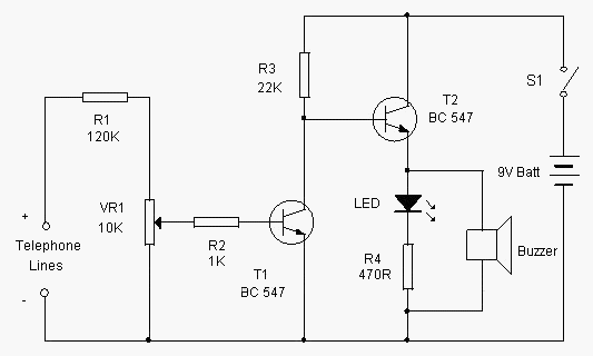
This simple circuit can indicate a misuse or tapping of Telephone line through a loud alarm. The circuit is too simple and can be easily assembled on a common PCB. Line voltage of Telephone lines is around 48 volts DC in the On hook state. When the handset is lifted, this voltage reduces to 12 volt DC. This change in voltage level is used to activate the circuit.When the switch S1 is closed, circuit becomes active and the telephone enters into the armed state.

The high volt DC from the telephone line passes through R1 and VR1 and bias T1 into conduction. As a result, the collector of T1 goes to ground potential to inhibit T2 from conduction. Buzzer and LED thus remain off. When the handset is lifted, the DC voltage from the telephone lines drops to 12 volts. This turns off T1 and T2 conducts. Buzzer beeps and LED lights indicating that the telephone is using.

Telephone Tapping Indicator Circuit

Circuit Project: Telephone Tapping Indicator

Setting
Connect the circuit to Telephone lines using a telephone plug. The free socket of the telephone or Caller ID can be used. Close S1 and adjust VR1 till buzzer stops beeping. Lift the handset. Buzzer should sound. Otherwise, just adjust VR1 till buzzer beeps.
Read More..

mobile phone jammer is installed in the hallway of every floor

 mobile phone jammer is installed in the hallway of every floor.
Sun at age 16 moved to the United States, California, and the learning of the University of California at Berkeley, majoring in Economics. School, where he invented a pocket translator, and applied for a patent, after the price of one million U.S. dollars, to sell translator Sharp company. Later created the Unison, the company is now for all Kyocera. Sun back to the Japanese banking software company, founded in 1981, the goal is to popularize computer knowledge to the Japanese. Early development of the Internet, Sun to his unique vision and courage to invest a large number of successful Internet startups including Yhaoo, ETrade, Softbank deservedly stood in the forefront of the Internet revolution. Source: to Pconline keep abreast 0 mobile phone to see news in 2001, Softbank opening of the Yahoo. BB business broadband ADSL services to subscribers in Japan. Moreover, installation of intelligent management system of school mobile phone jammer doesn’t shield the cell phone signal all day.Existing Industrial Park, 13, 30 overseas factories and manufacturing base, and eight overseas design center, 58800, marketing outlets. Huawei - Huawei is one of the global communications industry, a leading supplier of communications equipment R & D, production, marketing and service for customers around the world in the field of telecommunications network equipment to provide innovative, customized, services and solutions to achieve the customers potential for growth, sustained long-term value for our customers. As of October 2005, Huawei in the international market covering over 90 countries and regions in the worlds top 50 operators, 22 the use of Huaweis products and services. It is the examination room shielding of imported mobile phone jammer .
The biggest bright spot of the mobile advertising mobile phones and advertising combine to form a tripartite benefit of customers, businesses and carriers situation. 1.3 Analysis of mobile advertising -2 1.3.1 - Changsha Aeronautical Vocational and Technical College thesis a mobile advertising overall situation of the mobile advertising market analysis with the development of mobile communication technology, the 3G service model continues to become clear, mobile service model derived into innovation The change of phase. With mobile phones, known as the "media" and the term "mobile advertising" began to frequent exposure. U.S. market research firm Visiongains market report said, three years later, the U.S. and European mobile phone advertising market will reach about $ 1 billion. It is the specific school imported mobile phone jammer .
The problems of mobile advertising and defective defective mobile advertising: First, the boycott of mobile phone users on the ad. The current development of mobile advertising, due to the lack of relevant laws and regulations, advertising operators without mobile phone users any license on any advertising, -8 - 3 mobile advertising application and operation of Changsha Aeronautical Vocational and Technical College Thesis mode analysis is commonplace.
Read More..

Auto Anti Hijack Alarm Circuit Diagram

This Auto Anti-Hijack Alarm Circuit Diagram was designed primarily for the situation where a hijacker forces the driver from the vehicle. If a door is opened while the ignition is switched on - the circuit will trip. After a few minutes delay - when the thief is at a safe distance - the Siren will sound.

Auto Anti-Hijack Alarm Circuit Diagram

Where it differs from the first two alarms - is in what happens next. Im obliged to Victor Montanez from the USA who suggested that the engine cut-out should not operate - until the vehicle comes to a stop. That way - the engine will not fail suddenly or unexpectedly. And the hijacker will retain control.

I havent been able to implement Victors excellent suggestion completely - because I couldnt think of a simple, reliable and universally applicable way of sensing when the vehicle has come to a stop.

Instead - I have postponed engine failure until the ignition is switched off. Once the thief turns off the ignition - the engine will not re-start. Clearly - there is no certainty as to when this will occur. But I think it will occur sooner rather than later. Because theres a strong possibility that the hijacker will turn off the ignition - in an attempt to silence the siren. 

 Auto Anti-Hijack Alarm Circuit Diagram

Auto Anti-Hijack Alarm Circuit Diagram


As well as acting as a Hijack Alarm - this circuit offers some added protection. Like the Enhanced Hijack Alarm - it incorporates Jeff Chias suggestion. That is - every time the ignition is switched on - the alarm will trip. So it will protect the vehicle whenever you leave it unattended with the ignition switched off - even overnight in your driveway.

Importance
Before fitting this or any other engine cut-out to your vehicle - carefully consider both the safety implications of its possible failure - and the legal consequences of installing a device that could cause an accident. If you decide to proceed - you will need to use the highest standards of materials and workmanship.

Notes
Youre going to trip this alarm unintentionally. When you do - the LED will light and the Buzzer will give a short beep. The length of the beep is determined by C4. Its purpose is to alert you to the need to push the reset button. When you push the button - the LED will switch-off. Its purpose is to reassure you that the alarm has in fact reset. 

If the reset button is not pressed then - about 3 minutes later - both the Siren and the Buzzer will sound continuously. The length of the delay is set by R8 & C5. For extra effect - fit a second siren inside the vehicle. With enough noise going on - you may feel that its unnecessary to fit the engine cut-out. In which case - you can leave out C7, D8, R12, R13, Ty1 & Ry2.

When the ignition is switched on - C3 & R4 are responsible for tripping the alarm. By taking pin 1 low momentarily - they simulate the opening of a door. If you dont want the alarm to trip every time you turn on the ignition - simply leave out C3 & R4. 

Because the voltage on C3 may be reversed - the capacitor needs to be non-polarized. But connecting two regular 22uF capacitors back to back as shown - will work just as well. Because non-polarized capacitors are not widely available - the prototype was built using two polarized capacitors.

To reset the circuit you must - EITHER turn off the ignition - OR close all of the doors - before you press the reset button. While BOTH the ignition is on - AND a door remains open - the circuit will NOT reset.

The reset button carries virtually no current - so any small normally-open switch will do. Eric Vandel from Canada suggests using a reed-switch hidden behind (say) the dash - and operated by a magnet. I think this is an excellent idea. As Eric said in his email: - "... that should keep any thief guessing for a while."

Veroboard Layout

Veroboard Layout
 
How you prevent the engine from starting is up to you. It should happen when Ry2 de-energizes. The contacts of Ry2 are too small to do the job themselves. So use them to switch the coil of a larger relay. Remember that the relay must be suitable for the current its required to carry. Choose one specifically designed for automobiles - it will be protected against the elements - and will give the best long-term reliability. You dont want it to let you down on a cold wet night - or worse still - in fast moving traffic!!! Remember also that you must fit a 1N4001 diode across YOUR relays coil - to prevent damage to the Cmos IC
YOUR relay should drop-out when Ry2 de-energizes. Wire YOUR relay so that when it drops-out the engine will not start. Because turning-off the ignition will cause both Ry2 and YOUR relay to de-energize - the standby current will be low - and the engine will be disabled while the vehicle is parked.
The circuit board must be protected from the elements. Dampness or condensation will cause malfunction. Fit a 1-amp in-line fuse AS CLOSE AS POSSIBLE to your power source. This is VERY IMPORTANT. The fuse is there to protect the wiring - not the components on the circuit board. Please note that I am UNABLE to help any further with either the choice of a suitable relay - or with advice on installation.
Both the Siren and the Buzzer will go on sounding until the alarm is reset. The circuit is designed to use an electronic Siren drawing up to about 500mA. Its not usually a good idea to use the vehicles own Horn because it can be easily located and disconnected. However, if you choose to use the Horn, remember that Ry1 is too small to carry the necessary current. Connect the coil of a suitably rated relay to the "Siren" output. This can then be used to sound the Horn.


Read More..

Build a Simple Emergency Light and Alarm Circuit Diagram

This Simple Emergency Light and Alarm Circuit Diagram is permanently plugged into a mains socket andNI-CD batteries are trickle-charged. When a power outage occurs,the lamp automatically illuminates. Instead of illuminating alamp, an alarm sounder can be chosen.When power supply is restored, the lamp or the alarm isswitched-off. A switch provides a “latch-up” function, in orderto extend lamp or alarm operation even when power is restored.Circuit operation:Mains voltage is reduced to about 12V DC at C2`s terminals, bymeans of the reactance of C1 and the diode bridge (D1-D4). Thusavoids the use of a mains transformer.

 Simple Emergency Light and Alarm Circuit Diagram

Simple Emergency Light and Alarm Circuit Diagram


Trickle-charging current for the battery B1 is provided by theseries resistor R3, D5 and the green LED D6 that also monitorsthe presence of mains supply and correct battery charging.Q2 & Q3 form a self-latching pair that start operatingwhen a power outage occurs. In this case, Q1 biasing becomespositive, so this transistor turns on the self latching pair.

If SW3 is set as shown in the circuit diagram, the lampilluminates via SW2, which is normally closed; if set the otherway, a square wave audio frequency generator formed by Q4, Q5 andrelated components is activated, driving the loudspeaker.If SW1 is left open, when mains supply is restored the lamp orthe alarm continue to operate. They can be disabled by openingthe main on-off switch SW2.If SW1 is closed, restoration of the mains supply terminateslamp or alarm operation, by applying a positive bias to the Baseof Q2.

Notes:

Close SW2 after the circuit is plugged.Warning! The circuit is connected to 220Vac mains, then some parts in the circuit board are subjected to lethal potential! avoid touching the circuit when plugged and enclose it in a plastic box. 

Parts List
R1____________220K 1/4W Resistor
R2____________470R 1/2W Resistor
R3____________390R 1/4W Resistor
R4______________1K5 1/4W Resistor
R5______________1R 1/4W Resistor
R6_____________10K 1/4W Resistor
R7____________330K 1/4W Resistor
R8____________470R 1/4W Resistor
R9____________100R 1/4W Resistor

C1____________330nF 400V Polyester Capacitor
C2_____________10΅F 63V Electrolytic Capacitor
C3____________100nF 63V Polyester Capacitor
C4_____________10nF 63V Polyester Capacitor

D1-D5________1N4007 1000V 1A Diodes
D6______________LED Green (any shape)
D7___________1N4148 75V 150mA Diode

Q1,Q3,Q4______BC547 45V 100mA NPN Transistors
Q2,Q5_________BC327 45V 800mA PNP Transistors

SW1,SW2________SPST Switches
SW3____________SPDT Switch

LP1____________2.2V or 2.5V 250-300mA Torch Lamp

SPKR___________8 Ohm Loudspeaker

B1_____________2.5V Battery (tw1o AA NI-CD rechargeable cells wired in series)

PL1____________Male Mains plug

Read More..

Diode Cmos Stabilizer Circuit Diagram

The simple diode network can stabilize the voltage supplied to CMOS circuitry from a battery. D1 and D2 must have a combined forward-voltage drop of about 1.5 V. And D3 is an LED with a forward-voltage drop of about 1.7 V. The table shows the network`s output voltage as the battery`s voltage declines.


Diode Cmos Stabilizer Circuit Diagram

Diode Cmos Stabilizer Circuit Diagram

Read More..

Wednesday, December 25, 2013

18W Car Stereo Amplifier Rise

This automobile stereo amplifier project is a class AB audio power amplifier using the Hitachi HA13118 module. It not only can be used in automobile application but also in any transportable or home amplifier process. It is simple to construct & has a maximum of outside parts. The module has a high power output from a low voltage supply using the bridge tied load system, & a high gain of 55dB.

This project will be useful in applications where the input signal is a low level, without requiring the use of a separate pre-amplifier. This IC module has a built in surge protection circuit, thermal shutdown circuit, ground fault protection circuit & power supply fault protection circuit making it reliable.
The Specifications of this project 
D.C. Input : 8 – 18V at 1-2 A

Power output : 18W maximum, 4 ohm load, 18V DC supply

S/N ratio : > 70 dB

THD : < 0.2% @ 1W

Freq. Response : ~ 30 Hz to 30 kHz, –3 dB

Input level : < 25 mV, for full output (G > 50dB)

Input Impedance : ~ 30 k ohm

The supply voltage necessary for this project is 8 -18V DC, at least one to two Amps. Maximum output power will only be obtained with a power supply of 18V at greater than two A, using a four ohm speaker. The power supply ought to be well filtered to reduce mains hum, a regulated supply will reduce noise even further. Additional filtering is unnecessary if operating from a battery supply.

Circuit Diagram Description

Most of the circuitry is contained within the amplifier module. C10 is the input coupling capacitor and blocks DC from the input. C11 bypasses any RF which may be present at the input. C1 & C2 provide an AC ground for the inverting inputs of the IC. R1/C7 and R2/C8 provide a high frequency load for stability with difficult speakers. C five & C six provide bootstrap feedback for the IC. C9 & C12 provide power supply filtering.

18W Car Stereo Amplifier (Rise)

An externally mounted logarithmic potentiometer of between 10k ohm and 50k ohm, is used depending on the desired input impedance. The impedance ought to be keep as high as feasible for a guitar amp, unless using a separate pre-amp. Make sure-that the heat sink is mounted to the module.


Read More..

Spy Camera Solar Power Box

Battery life has always been a critical consideration for most of the electronic gadgets and equipment. When we talk about spy  cameras,  which  normally  function  round-the-clock, they often run out of power within a few days.  Many spy cameras (CCTV cameras) are powered by 9V PP3 type batteries that offer five times more energy  than the regular 9V alkaline battery.

Mini CCTV cameras also accept 6-12V DC supply from AC mains adaptor through the DC IN jack. AC mains adaptor for the camera increases the capacity of the 9V PP3 battery but is bulky and noisy. Whether disposable  or rechargeable batteries, making frequent replacement or recharging them is a cumbersome job. The unique solar power box described here serves an alternative solution to the problem. 

Spy Camera Solar Power Box Circuit diagram :

Spy Camera Solar Power Box-Circuit Daigram

The circuit of the solar power box is simple. It contains a  battery charger and a battery health indicator and  a few other components.  As shown in the circuit,  DC supply available from  the solar panel (SP1) is  directly applied to the in-put of the circuit through  a protection diode (D1).  This diode is used to pre-vent  the  reverse  current  flow from the battery to  the  solar  panel  during  night. Thus, D1 allows  the current to flow from the solar panel  to the battery only. Low-voltage-drop  type 1N5817 diode is perfect for the  job.
At the heart of the circuit is an integrated current source, realised using a  popular 3-pin adjustable voltage regulator LM317T(IC1). 

This IC is designed  to adjust its internal resistance between  the In (pin 3) and Out (pin 2) terminals  to maintain a constant voltage of 1.25V  between the Out (pin 2) and Adj (pin 1) terminals. Here, a 9V, 280 mAh  rechargeable PP3 type Ni-MH battery  (BATT) is used as reservoir. Normally,  a charging current of about 10 per cent  of  ampere-hour  rating  is  safe  for  the  battery. Resistor R1 (39-ohm, 0.5W),  connected between pin 1 and 3 of IC1,  limits  the  charging  current  to  about  30 mA. DC output from the battery is  available at output jack J2. Red LED  ( LED1) is used as a battery ‘health’  indicator. Switch S1 is used to start the  charging while S2 is used for connect-ing the load. Note that suitable heat  sink should be used for the IC1.

The proper selection of solar panel  is important but not critical. A miniature 12V type solar panel with a cur-rent output of about 100 mA can be  used. Even if you have a solar panel  with  higher  voltage  rating,  it  will  not  create a problem as the circuit ensures  that the charging current cannot exceed  the predetermined value.

The circuit can be easily assembled  on a general-purpose PCB and housed  in a small plastic cabinet.

Source :  http://www.ecircuitslab.com/2012/05/spy-camera-solar-power-box.html
Read More..

Cash Box Guard

Most thefts happen after midnight when people enter the second phase of sleep called paradoxical sleep. Here is a smart security circuit for your cash box that thwarts the theft attempt by activating an emergency beeper. The circuit can also be used to trigger any external burglar alarm unit. The cash box guard circuit (shown in Fig. 1) is built around IC CD4060 (IC1), which has an inbuilt oscillator and divider. The basic oscillator is configured by a simple resistor-capacitor (R-C) network. IC CD4060 divides this oscillator frequency into binary divisions, which are available as outputs.

In light, reset pin 12 of IC1 remains low, which enables the oscillator built around IC1. However, in the dark, it making all the outputs low. This also stops oscillations of the internal oscillator. Working of the circuit is simple. If the cash box is closed, the interior will be dark. Hence in the dark, the light-dependant resistor (LDR1) resets IC1 and it stops oscillating and counting. At the same time, pins 13 and 14 of IC1 go low. So neither the piezobuzzer (PZ1) sounds, nor the relay (RL1) energises, indicating that the cash box is closed.

Cash Box Guard circuit diagram
Fig. 1: Cash box guard circuit

If someone tries to open the door of the cash box, light-most probably from the burglars pen torch -falls on LDR1 fitted into the cash box. As a result, LDR1 conducts and pin 12 of IC1 goes low. IC1 starts oscillating and counting. With the present timing R-C components (at pins 9, 10 and 11), the output timing at pin 14 of IC1 is two-three seconds. Hence pin 14 of IC1 goes high for two seconds after the door is opened and goes low for another two seconds. So the piezobuzzer (PZ1) sounds for two seconds and then falls silent for the following two seconds. This cycle repeats until the cash box is closed.

An optional relay is added for a remotely located audio/visual alert system. For that, a relay driver circuit built around npn transistor BC548 (T2) is used. The relay is energised by the output from pin 13 of IC1 for about four seconds after the door is opened and then de-energised for the following four seconds. You can use this relay to activate another remotely located audio/visual alert system. After assembling the circuit on a small PCB, house it in a small tamper-proof box (refer Fig. 2) leaving a little window for LDR1 and a small opening for the piezobuzzer (PZ1). Now fit the unit inside the cash box (refer Fig. 3) with LDR1 pointing towards the door of the cash box.


Fig. 2: Assemble unit

Note:
  1. The relay latching facility can be added to the circuit by replacing transistor T2 with a suitable silicon-controlled rectifier such as BT169.
  2. By changing the value of resistor R1, you can adjust the light detection sensitivity of the circuit.
  3. If you want to use a 3-pin piezobuzzer device, remove buzzer-driver npn transistor T1 and connect trigger pin of the buzzer directly to pin 14 of IC1. Also connect the positive and negative terminals of the buzzer to respective positive and negative points of the circuit.
  4. Photo-transistor 2N5777 can be used in place of the 10mm LDR1.

Fig. 3: Unit fitted inside the cash box & also connected to an external alarm
Read More..

Solar Cell


The circuit illustrated below is used as Solar Cell. You can get plate from your old faulty solar calculator. Carefully dissemble plate with out tearing its 2 wire. Connect both wire to a LED through a switch. When Solar Plate is kept in sunlight and switched ON you will see LED glows .
 Please make sure for the correct polarity of LED.
Theory :
    When energy is added to pure silicon, for example in the form of heat, it can cause a few electrons to break free of their bonds and leave their atoms. A hole is left behind in each case. These electrons then wander randomly around the crystalline lattice looking for another hole to fall into. These electrons are called free carriers, and can carry electrical current
Solar Plate can be made by :
Step 1
Stain the Titanium Dioxide with the Natural Dye
Step 2
Coat the Counter Electrode
Step 3
Add the Electrolyte and Assemble the Finished Solar Cell

            How Solar System Works ? Learn by Animation
Read More..

Switch Selected Fixed Voltage Power Supply Circuit Diagram

This Switch Selected Fixed Voltage Power Supply Circuit Diagram can serve as a battery eliminator for various devices (such as tape recorders, small radios, clocks, etc.). Si selects a resistance that is predetermined to provide a preselected output voltage. In this circuit, various commonly used supply voltages produced by batteries were chosen, but any voltages up to the rating of Tl (approximately) can be produced by choosing an appropriate resistor. Remember to provide adequate heatsinking for Ul.


Switch Selected Fixed Voltage Power Supply Circuit Diagram


Switch Selected Fixed Voltage Power Supply Circuit Diagram

Read More..

Tuesday, December 24, 2013

Speed Limit Alert

Wireless portable unit, Adaptable with most internal combustion engine vehicles
This circuit has been designed to alert the vehicle driver that he/she has reached the maximum fixed speed limit (i.e. in a motorway). It eliminates the necessity of looking at the tachometer and to be distracted from driving. There is a strict relation between engines RPM and vehicle speed, so this device controls RPM, starting to beep and flashing a LED once per second, when maximum fixed speed is reached. Its outstanding feature lies in the fact that no connection is required from circuit to engine.
Circuit operation:
IC1 forms a differential amplifier for the electromagnetic pulses generated by the engine sparking-plugs, picked-up by sensor coil L1. IC2A further amplifies the pulses and IC2B to IC2F inverters provide clean pulse squaring. The monostable multivibrator IC3A is used as a frequency discriminator, its pin 6 going firmly high when speed limit (settled by R11) is reached. IC3B, the transistors and associate components provide timings for the signaling part, formed by LED D5 and piezo sounder BZ1. D3 introduces a small amount of hysteresis.

Speed-limit Alert Circuit Diagram

Parts:
R1,R2,R19_______1K 1/4W Resistors
R3-R6,R13,R17_100K 1/4W Resistors
R7,R15__________1M 1/4W Resistors
R8_____________50K 1/2W Trimmer Cermet
R9____________470R 1/4W Resistor
R10___________470K 1/4W Resistor
R11___________100K 1/2W Trimmer Cermet (see notes)
R12___________220K 1/4W Resistor (see notes)
R14,R16________68K 1/4W Resistors
R18____________22K 1/4W Resistor
R20___________150R 1/4W Resistor (see notes)
C1,C7_________100µF 25V Electrolytic Capacitors
C2,C3_________330nF 63V Polyester Capacitors
C4-C6___________4µ7 25V Electrolytic Capacitors
D1,D5______Red LEDs 3 or 5mm.
D2,D3________1N4148 75V 150mA Diodes
D4________BZX79C7V5 7.5V 500mW Zener Diode
IC1__________CA3140 or TL061 Op-amp IC
IC2____________4069 Hex Inverter IC
IC3____________4098 or 4528 Dual Monostable Multivibrator IC
Q1,Q2_________BC238 25V 100mA NPN Transistors
L1_____________10mH miniature Inductor (see notes)
BZ1___________Piezo sounder (incorporating 3KHz oscillator)
SW1____________SPST Slider Switch
B1_______________9V PP3 Battery (see notes) Clip for PP3 Battery

Notes:
  • D1 is necessary at set-up to monitor the sparking-plugs emission, thus allowing to find easily the best placement for the device on the dashboard or close to it. After the setting is done, D1 & R9 can be omitted or switched-off, with battery savings.
  • During the preceding operation R8 must be adjusted for better results. The best setting of this trimmer is usually obtained when its value lies between 10 and 20K.
  • You must do this first setting when the engine is on but the vehicle is stationary.
  • The final simplest setting can be made with the help of a second person. Drive the vehicle and reach the speed needed. The helper must adjust the trimmer R11 until the device operates the beeper and D5. Reducing vehicles speed the beep must stop.
  • L1 can be a 10mH small inductor usually sold in the form of a tiny rectangular plastic box. If you need an higher sensitivity you can build a special coil, winding 130 to 150 turns of 0.2 mm. enameled wire on a 5 cm. diameter former (e.g. a can). Extract the coil from the former and tape it with insulating tape making thus a stand-alone coil.
  • Current drawing is about 10mA. If you intend to use the car 12V battery, you can connect the device to the lighter socket. In this case R20 must be 330R.
  • Depending on the engines cylinders number, R11 can be unable to set the device properly. In some cases you must use R11=200K and R12=100K or less.
  • If you need to set-up the device on the bench, a sine or square wave variable generator is required.
  • To calculate the frequency relation to RPM in a four strokes engine you can use the following formula: Hz= (Number of cylinders * RPM) / 120.
  • For a two strokes engine the formula is: Hz= (Number of cylinders * RPM) / 60.
  • Thus, for a car with a four strokes engine and four cylinders the resulting frequency @ 3000 RPM is 100Hz.
  • Temporarily disconnect C2 from IC1 pin 6. Connect the generator output across C2 and Ground. Set the generator frequency to e.g. 100Hz and trim R11 until you will hear the beeps and LED D5 will start flashing. Reducing the frequency to 99 or 98 Hz, beeping and flashing must stop.
  • Please note that this circuit is not suited to Diesel engines.
Source :  http://www.ecircuitslab.com/2011/06/speed-limit-alert.html
Read More..

Versatile Micropower Battery Protector

Protect your expensive batteries from discharge damage with this mini-sized electronic cutout switch. It uses virtually no power and can be built to suit a wide range of battery voltages.
Main Features
  • Disconnects load at preset battery voltage
  • Automatically reconnects load when battery recharged
  • Ultra-low power consumption (<20ma)
  • Miniature size
  • 10A maximum rating
  • Suitable for use with 4.8-12.5V batteries
  • Transient voltage protection (optional)
Suitable for use in...
  • Cars, boats & caravans
  • Security systems
  • Emergency lighting
  • Small solar installations
  • Camera battery packs
  • Many other low-power applications
Picture of the project:
versatile-micropower-battery-protector-circuit1
versatile-micropower-battery-protector-circuit-backside 2
Back in May 2002, we (Silicon Chip) presented the "Battery Guardian", a project designed specifically for protecting 12V car batteries from over-discharge. This unit has proven to be very popular and is still available from kit suppliers. This new design does not supersede the Battery Guardian – at least not when it comes to 12V car batteries. Instead, it’s a more flexible alternative that can be used with a wide range of battery voltages.
Parts layout:
front-parts-layout-versatile-micropower-battery-protector-circuit 3
back-parts-layout-versatile-micropower-battery-protector-circuit 4
In this new "Micropower Battery Protector", we’ve dispensed with the low-battery warning circuitry and the relatively cheap N-channel MOSFET used in the Battery Guardian in favour of a physically smaller module that steals much less battery power. It costs a little more but can switch lower voltages, allowing it to be used with 6V & 12V lead-acid batteries and 4-cell to 10-cell NiCd and NiMH battery packs.
PCB layout:
pcb-layout-versatile-micropower-battery-protector-circuit 5
Most battery-powered equipment provides no mechanism for disconnecting the batteries when they’re exhausted. Even when the voltage drops too low for normal operation, battery drain usually continues until all available energy is expended. This is particularly true of equipment designed to be powered from alkaline or carbon cells but retro-fitted with rechargeables.
Circuit diagram:
versatile-micropower-battery-protector-circuit-diagram 6
Another example is emergency lighting and security equipment designed to be float-charged from the mains. In an extended blackout period, the batteries can be completely drained and may not recover when the mains power is finally restored.

Source:   http://www.ecircuitslab.com/2011/06/versatile-micropower-battery-protector.html
Read More..

Water level indicator


Water Level Indicator

Description

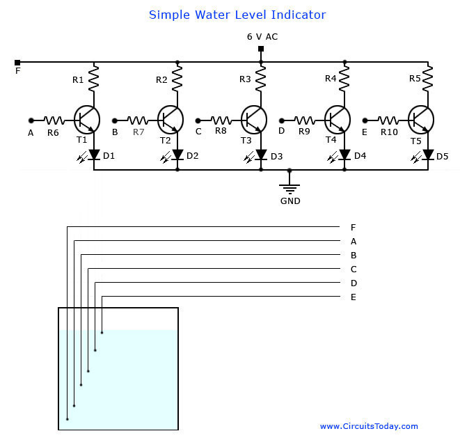
This is the circuit diagram of a simple corrosion free water level indicator for home and industries. In fact the the level of any conductive non corrosive liquids can be measured using this circuit. The circuit is based on 5 transistor switches. Each transistor is switched on to drive the corresponding LED , when its base is supplied with current through the water through the electrode probes.
One electrode probe is (F) with 6V AC is placed at the bottom of tank. Next probes are placed step by step above the bottom probe. When water is rising the base of each transistor gets electrical connection to 6V AC through water and the corresponding probe. Which in turn makes the transistors conduct to glow LED and indicate the level of water. The ends of probes are connected to corresponding points in the circuit as shown in circuit diagram.Insulated Aluminum wires with end insulation removed will do for the probe. Arrange the probes in order on a PVC pipe according to the depth and immerse it in the tank.AC voltage is use to prevent electrolysis at the probes. So this setup will last really long. I guarantee at least a 2 years of maintenance free operation. That’s what I got and is still going.

Components

T1 – T5 BC 548 or 2N2222 Transistors
R1-R5 2.2K 1/4 W Resistors
R6-R10 22K 1/4 W Resistors
D1 – D5 LED’s ( color your choice)

Notes:

Use a transformer with 6V 500 mA output for power supply. Do not use a rectifier! we need pure AC. Use good quality insulated Aluminum wire for probes. If Aluminum wires are not available try Steel or Tin.Copper is the worst. Try the circuit first on a bread board and if not working properly, make adjustments with the resistance values. This is often needed because conductivity of water changes slightly from place to place. The type number of the transistors used here are not critical and any small signal NPN transistor will do the job. Few other suitable type numbers are BC546, BC107, PN2222, BC337, BF494, ZTX300, BEL187 etc. The circuit can be enclosed in a plastic box with holes for revealing the LEDs .

Water Level Indicator Circuit Diagram and Sensor Arrangement.


Water Level Indicator Circuit
Water Level Indicator
Read More..

Monday, December 23, 2013

4 Bit Analogue to Digital Converter

The operation of the converter is based on the weighted adding and transferring of the analogue input levels and the digital output levels. It consists of comparators and resistors. In theory, the number of bits is unlimited, but each bit needs a comparator and several coupling resistors. The diagram shows a 4-bit version. The value of the resistors must meet the following criteria:
  • R1:R2 = 1:2;
  • R3:R4:R5 = 1:2:4;
  • R6:R7:R8:R9 = 1:2:4:8.
The linearity of the converter depends on the degree of precision of the value of the resistors with respect to the resolution of the converter, and on the accuracy of the threshold voltage of the comparators. This threshold level must be equal, or nearly so, to half the supply voltage. Moreover, the comparators must have as low an output resistance as possible and as high an input resistance with respect to the load resistors as feasible. Any deviation from these requirements affects the linearity of the converter adversely.

4-Bit Analogue to Digital Converter Circuit diagram :


If the value of the resistors is not too low, the use of inverters with an FET (field-effect transistor) input leads to a near-ideal situation. In the present converter, complementary metal-oxide semiconductor (CMOS) inverters are used, which, in spite of their low gain, give a reasonably good performance. If standard comparators are used, take into account the output voltage range and make sure that the potential at their non-inverting inputs is set to half the supply voltage. If high accuracy is a must, comparators Type TLC3074 or similar should be used. This type has a totem-pole output.

The non-inverting inputs should be interlinked and connected to the tap of a a divider consisting of two 10 kΩ resistors across the supply lines. It is essential that the converter is driven by a low-resistance source. If necessary, this can be arranged via a suitable op amp input buffer. The converter draws a current not exceeding 5 mA.

Source :http://www.ecircuitslab.com/2011/07/4-bit-analogue-to-digital-converter.html
Read More..

Quality Stereo Wireless Microphone or Audio Link

This stereo FM wireless microphone also makes a great quality audio link. We tested it to beyond 50 meters and it was rock solid. It’s certainly not the first wireless microphone we’ve ever published but this one is a little different. It’s stereo, providing surprisingly good quality sound. Second, it has a really good range. We tested it at well over 50m and it was still performing very well – noise-free, in fact – but at the time we couldn’t get our receiver any further away. So it’s likely to have even better range than that.

Complete Project:

quality stereo wireless microphone or audio link schematic circuit diagram

Its easy to build, requires very little setup... and its cheap! In fact, the low price might turn some people off, thinking its low quality. Try it - and be pleasantly surprised! Third, it really is simple to build – the hard work (the transmitter module) is already done for you. It’s just a matter of assembling the microphone module, which contains the electret mics themselves, preamp and level controls, and soldering the transmitter module onto it, "piggy back" style.

FM Transmitter:


Finally, the transmitter module is crystal-locked, so you won’t have the drift probles of some earlier wireless microphones. And just in case you were wondering, that doesn’t mean the output is locked to one particular frequency – it has a nifty synthesis circuit built in to give you the choice of seven different frequencies between 106.7MHz and 107.7MHz. On-board preset pots adjust the sensitivity of each channel to take into account mic differences or if you require different levels in each channel.

FM transmitter circuit schematic

By the way, the transmitter module is quite capable of operating at line level if you want just a line level transmitter (eg, to feed an audio program around your home). Sensitivity is about 100mV. Oatley Electronics, who designed the kit, have the transmitter module available by itself if that’s what you’re after. But more on that anon.

FM transmitter circuit schematic

Parts Layout:

FM transmitter circuit schematic

FM transmitter circuit schematic

You also have the choice of two power supply levels – 3-6V or 7-15V DC. The latter results in a lower current drain. The transmitter module also has a "5V out" rail to supply power to the preamp module.

Circuit Diagram:

Quality Stereo Wireless Microphone or Audio Link Schematic Circuit Diagram

Two electret microphone inserts are supplied in the kit. These can be soldered direct to the PC board to make it a fully self-contained project or they can be attached to the board via suitable lengths of mini shielded coax cable. A third option is to use "proper" microphones – they can be electret or dynamic types – but no provision has been made for plugging these in.

Typical Specifications:

Audio response:.....................20Hz-15kHz.
Channel separation: ........................40dB
Total Harmonic Distortion: ...............0.1%
Output Frequency:...........106.7-107.2MHz
Pre Emphasis: ..................................50μS
DC supply voltage range: ................3-15V
Supply Current: .......................30mA @ 9V
Source: Silicon Chip 28 May 2005
Read More..

Boost Current Upgrade Your USB Hub

Problems can arise with USB hubs that are powered from a PC when gadgets plugged into them draw too much current. This is often the case with devices fitted with USB cables that are too long or too thin, causing voltage drop. There’s no need to scrap your old USB hub, however, if you upgrade it using this little circuit and an external power supply.

Just cut the 5-V power wire of the USB cable inside the hub and solder a diode (D1) in the pass-through direction. Now connect the 5 V wire from the external power supply to the cathode of this diode. D1 prevents any current from the power supply from flowing back into the PC.

Read More..

This is the latest telecom industry boom

 This is the"

shared channels between Siemens and Bird "After another Chinese-foreign cooperation. cooperation is limited to selling cell phones yesterday, the reporter was informed by insiders from Motorola,

start from December 1, Motorola and strategic cooperation between TCL Mobile will be fully launched. Nokias enterprise voice business executives Jacques ? Aoke Ning said: "For large enterprises

using wireless communication technology is just unrealistic, fixed-line telecell phone has its place." Nokia claims that change is the emergence of the trend of convergence of fixed and wireless,

This is the latest telecom industry boom.Nokia estimated mobile voice communications in

the enterprise ICT spending accounted for 10% -25%, which is higher than any other business systems, including SAP and other costly systems. Telecom users to organize the Union of European Virtual

Private Network Xi Aide ? Funk said: "Mobility is a key element composition of staff efficiency, but the cost is high. Mobile environment should be suitable for private fixed-line environment, in

order to reduce costs."
Meanwhile, several major appliance stores from capital sales data show that since August this year, the proportion of multi-media cell phone sales increased month by month, the current mainstream

manufacturers usually have three to five models of multimedia products. Price in perspective, more than domestic brands in less than 3,000 yuan, while foreign brands are all in more than 5,000.

DoCoMos chief financial officer Yoshiaki Ugaki said the company next year will also provide users with Nokia and LG Electronics from foreign manufacturers of cell phones. Foreign production of

cell phone price up to 1 million yen (about $ 84), much lower than in Japan cell phone. Nearly 12 years, the Japanese government will release the first mobile license, which means that the Japanese

mobile communications market competition will become increasingly fierce.People can enjoy fastness and convenience brought by high technology including cell phone jammer .
"And the television, print media, the cell phone is still a narrow niche media, and even a few dollars more than twenty per SMS and MMS subscription fees, and high GPRS Internet access fees for

most users away." Jiang Lifeng have some concern.


Read More..

Circuit Diagram of Fire Alarm


   Here is a simple circuit which can be used as a Fire Alarm. 3 Volt is enough to operate. There is not much to the circuit. The IC UM66 is connected to its supply and its output fed to a transistor for amplification.
   UM66 is a complete miniature tone generator with a ROM of 64 notes, oscillator and a preamplifier. For amplification we have used a NPN transistor which is BC548. Here BC548 makes a common emitter circuit. For limiting the base current we have used a resistance of 220 Ohms so that transistor will not get damaged even if IC is wrong connected.
   For heat sensor we have used tube light starter in place of manual switch. In a starter there is a metal plate and a pin with small gap. When starter gets heated then metal plate of starter expands and get in contact with the pin and circuit is completed and we get audio from speaker. For fast sensing we can use starter without its glass body by carefully breaking glass cover.


Read More..

parallel and series circuit diagrams


Some viewers hadnt clear idea about parallel and series circuits.Here you can see  we can  build a  circuit in two ways they are parallel and series.If I explain simply when you use series circuit it will reduce the light of the bulb according to the number of bulbs  but when you use parallel circuit diagram it will not reduce the light of the bulb but it will drain your battery speedly 
 
Read More..

Sunday, December 22, 2013

Hybrid Headphone Amplifier

Potentially, headphone listening can be technically superior since room reflections are eliminated and the intimate contact between transducer and ear mean that only tiny amounts of power are required. The small power requirement means that transducers can be operated at a small fraction of their full excursion capabilities thus reducing THD and other non-linear distortions. This design of a dedicated headphones amplifier is potentially controversial in that it has unity voltage gain and employs valves and transistors in the same design. Normal headphones have an impedance of 32R per channel. The usual standard line output of 775 mV to which all quality equipment aspires will generate a power of U2 / R = 0.7752 / 32 = 18 mW per channel across a headphone of this impedance.
An examination of available headphones at well known high street emporiums revealed that the sensitivity varied from 96 dB to 103db/mW! So, in practice the circuit will only require unity gain to reach deafening levels. As a unity gain design is required it is quite possible to employ a low distortion output stage. The obvious choice is an emitter follower. This has nearly unity gain combined with a large amount of local feedback. Unfortunately the output impedance of an emitter follower is dependent upon the source impedance. With a volume control, or even with different signal sources this will vary and could produce small but audible changes in sound quality.
To prevent this, the output stage is driven by a cathode follower,based around an ECC82 valve (US equivalent: 12AU7).
This device, as opposed to a transistor configuration, enables the output stage to be driven with a constant value, low impedance. In other words, the signal from the low impedance point is used to drive the high impedance of the output stage, a situation which promotes low overall THD. At the modest output powers required of the circuit, the only sensible choice is a Class A circuit. In this case the much vaunted single-ended output stage is employed and that comprises of T3 and constant current source T1-T2.

Hybrid Headphone Amplifier Circuit Diagram


The constant current is set by the Vbe voltage of T1 applied across R5 With its value of 22R, the current is set at 27 mA. T3 is used in the emitter follower mode with high input impedance and low output impedance. Indeed the main problem of using a valve at low voltages is that it’s fairly difficult to get any real current drain. In order to prevent distortion the output stage shouldn’t be allowed to load the valve. This is down to the choice of output device. A BC517 is used for T3 because of its high current gain, 30,000 at 2 mA! Since we have a low impedance output stage, the load may be capacitively coupled via C4. Some purists may baulk at the idea of using an electrolytic for this job but he fact remains that distortion generated by capacitive coupling is at least two orders of magnitude lower than transformer coupling.
The rest of the circuitry is used to condition the various voltages used by the circuit. In order to obtain a linear output the valve grid needs to be biased at half the supply voltage. This is the function of the voltage divider R4 and R2. Input signals are coupled into the circuit via C1 and R1. R1, connected between the voltage divider and V1’s grid defines the input impedance of the circuit. C1 has sufficiently large a value to ensure response down to 2 Hz. Although the circuit does a good job of rejecting line noise on its own due to the high impedance of V1’s anode and T3’s collector current, it needs a little help to obtain a silent background in the absence of signal.
The ‘help’ is in the form of the capacitance multiplier circuit built around T5. Another BC517 is used here to avoid loading of the filter comprising R7 and C5. In principle the capacitance of C5 is multiplied by the gain of T5. In practice the smooth dc applied to T5’s base appears at low impedance at its emitter. An important added advantage is that the supply voltage is applied slowly on powering up. This is of course due to the time taken to fully charge C5 via R7. No trace of hum or ripple can be seen here on the ‘scope. C2 is used to ensure stability at RF. The DC supply is also used to run the valve heater. The ECC82 has an advantage here in that its heater can be connected for operate from 12.6 V. To run it T4 is used as a series pass element. Base voltage is obtained from the emitter of T5. T4 has very low output impedance, about 160 mR and this helps to prevent extraneous signals being picked up from the heater wiring. Connecting the transistor base to C5 also lets the valve heater warm up gently. A couple of volts only are lost across T4 and although the device runs warm it doesn’t require a heat-sink.

Source:  http://www.ecircuitslab.com/2011/06/hybrid-headphone-amplifier.html
Read More..

Thyristor Tester

The circuit in the diagram is a very handy tool for rapidly checking all kinds of thyristor (SCR, triac, …). In case of a triac, all four quadrants are tested, which is done with S3, while in case of a standard thyristor, a positive power supply and trigger current need to be set, which is done with S1. The value of resistors R1 and R2 is chosen to obtain a current of about 28mA, which is more than sufficient for most thyristors.

The hold current is determined by R3, and is 125 mA, which is more than adequate to keep the thyristor in conduction after it has been triggered. Since D1 is a red, low-current LED, and D2 a green, low-current LED, it can be seen in a wink in which quadrant the thyristor conducts.

Circuit diagram:

Thyristor Tester Circuit Diagram

Testing is started with S2, and the circuit is reset with S4 after the test has been concluded. Three short lengths of circuit wire terminated into insulated crocodile clips on connector K1 will be found very convenient for linking any kind of thyristor to the circuit. Mind correct connections, though: in the case of a triac, MT1/A1 is linked to earth, the gate to S2 and MT2/A2 to R3; in the case of a standard thyristor, the anode is linked to R3, the cathode to earth, and the gate to S2.

If, in a rare case the trigger current needs to be altered, this can be done by changing the value of resistors R1–R3 as appropriate. The trigger current may also be made variable by the use of a variable power supply. If that is done, make sure that the dissipation in the resistors is not exceeded.
Read More..

Moduler Audio Preamplifier

High Quality, Discrete Components Design, Input and Tone Control Modules
To complement the 60 Watt MosFet Audio Amplifier a High Quality Preamplifier design was necessary. A discrete components topology, using + and - 24V supply rails was chosen, keeping the transistor count to the minimum, but still allowing low noise, very low distortion and high input overload margin. Obviously, the modules forming this preamplifier can be used in different combinations and drive different power amplifiers, provided the following stages present a reasonably high input impedance (i.e. higher than 10KOhm).

Main Module:
If a Tone Control facility is not needed, the Preamplifier will be formed by the Main Module only. Its input will be connected to some sort of changeover switch, in order to allow several audio reproduction devices to be connected, e.g. CD player, Tuner, Tape Recorder, iPod, MiniDisc etc. The total amount and type of inputs is left to the choice of the home constructor. The output of the Main Module will be connected to a 22K Log. potentiometer (dual gang if a stereo preamp was planned). The central and ground leads of this potentiometer must be connected to the power amplifier input.

Main Module Circuit diagram:
Main Module Circuit Diagram
Parts:
R1_____________1K5 1/4W Resistor
R2_____________220K 1/4W Resistor
R3_____________18K 1/4W Resistor
R4_____________330R 1/4W Resistor
R5_____________39K 1/4W Resistor
R6_____________56R 1/4W Resistor
R7,R10_________10K 1/4W Resistors
R8_____________33K 1/4W Resistor
R9_____________150R 1/4W Resistor
R11____________ 6K8 1/4W Resistor
R12,R13________100R 1/4W Resistors
R14____________100K 1/4W Resistor
C1_____________220nF 63V Polyester Capacitor
C2_____________220pF 63V Polystyrene or ceramic Capacitor
C3_____________1nF 63V Polyester or ceramic Capacitor
C4,C7__________47µF 50V Electrolytic Capacitors
C5,C6__________100µF 50V Electrolytic Capacitors
Q1,Q2__________BC550C 45V 100mA Low noise High gain NPN Transistors
Q3_____________BC556 65V 100mA PNP Transistor
Q4_____________BC546 65V 100mA NPN Transistor

Tone Control Module:

This Module employs an unusual topology, still maintaining the basic op-amp circuitry of the Main Module with a few changes in resistor values. A special feature of this circuit is the use of six ways switches instead of the more common potentiometers: in this way, precise "tone flat" setting, or preset dB steps in bass and treble boost or cut can be obtained. Tone Control switches also allow a more precise channel matching when a stereo configuration is used, avoiding the frequent poor alignment accuracy presented by common ganged potentiometers. Six ways (two poles for stereo) rotary switches were chosen for this purpose as easily available. This dictated the unusual "asymmetrical" configuration of three positions for boost, one for flat and two for cut.
This choice was based on the fact that tone controls are used in practice more for frequency boosting than for cutting purposes. In any case, +5dB +10dB and +15dB of bass boost and -3dB and -10dB of bass cut were provided. Treble boost was also set to +5dB +10dB and +15dB and treble cut to -3.5dB and -9dB. Those wishing to use common potentiometers in the usual way for Tone Controls may use the circuit shown enclosed in the dashed box (bottom-right of the Tone Control Module circuit diagram) to replace switched controls. The Tone Control Module should usually be placed after the Main Input Module, and the volume control inserted between the Tone Control Module output and the power amplifier input. Alternatively, the volume control can also be placed between Main Input Module and Tone Control Module, at will. Furthermore, the position of these two modules can be also interchanged.

Tone Control Module Circuit diagram:

Tone Control Module Circuit Diagram

Parts:
R1,R7___________47K 1/4W Resistors
R2_____________220K 1/4W Resistor
R3______________18K 1/4W Resistor
R4_____________330R 1/4W Resistor
R5______________39K 1/4W Resistor
R6______________56R 1/4W Resistor
R8_____________150R 1/4W Resistor
R9______________10K 1/4W Resistor
R10,R16__________6K8 1/4W Resistors
R11,R12________100R 1/4W Resistors
R13____________100K 1/4W Resistor
R14______________1K5 1/4W Resistor
R15,R21,R22______4K7 1/4W Resistors
R17,R24,R26______8K2 1/4W Resistors
R18______________3K3 1/4W Resistor
R19______________1K 1/4W Resistor
R20____________470R 1/4W Resistor
R23,R25_________12K 1/4W Resistors
R27,R28__________4K7 1/4W Resistors
C1_____________220nF 63V Polyester Capacitor
C2_______________1nF 63V Polyester or ceramic Capacitor
C3,C6___________47µF 50V Electrolytic Capacitors
C4,C5__________100µF 50V Electrolytic Capacitors
C7______________10nF 63V Polyester Capacitor
C8,C9__________100nF 63V Polyester Capacitors
Q1,Q2_________BC550C 45V 100mA Low noise High gain NPN Transistors
Q3____________BC556 65V 100mA PNP Transistor
Q4____________BC546 65V 100mA NPN Transistor
SW1,SW2_______2 poles 6 ways Rotary Switches
Simpler, alternative Tone Control parts:
P1______________22K Linear Potentiometer
P2______________47K Linear Potentiometer
R29,R30________470R 1/4W Resistors
R31,R32__________4K7 1/4W Resistors
C10_____________10nF 63V Polyester Capacitor
C11,C12________100nF 63V Polyester Capacitors

Power supply:
The preamplifier must be feed by a dual-rail, +24 and -24V 50mA dc power supply. This is easily achieved by using a 48V 3VA center-tapped mains transformer, a 100V 1A bridge rectifier and a couple of 2200µF 50V smoothing capacitors. To these components two 24V IC regulators must be added: a 7824 (or 78L24) for the positive rail and a 7924 (or 79L24) for the negative one. The diagram of such a power supply is the same of that used in the Headphone Amplifier, but the voltages of the secondary winding of the transformer, smoothing capacitors and IC regulators must be uprated. Alternatively, the dc voltage can be directly derived from the dc supply rails of the power amplifier, provided that both 24V regulators are added.

Note:
If this preamplifier is used as a separate, stand-alone device, thus requiring a cable connection to the power amplifier, some kind of output short-circuit protection is needed, due to possible shorts caused by incorrect plugging. The simplest solution is to wire a 3K3 1/4W resistor in series to the output capacitor of the last module (i.e. the module having its output connected to the preamp main output socket).

Technical data:

Main Module Input sensitivity:
250mV RMS for 1V RMS output
Tone Control Module Input sensitivity:
1V RMS for 1V RMS output
Maximum output voltage:
13.4V RMS into 100K load, 11.3V RMS into 22K load, 8.8V RMS into 10K load
Frequency response:
flat from 20Hz to 20KHz
Total harmonic distortion @ 1KHz:
1V RMS 0.002% 5V RMS 0.003% 7V RMS 0.003%
Total harmonic distortion @10KHz:
1V RMS 0.003% 5V RMS 0.008% 7V RMS 0.01%

Source :http://www.ecircuitslab.com/2011/06/moduler-audio-preamplifier.html  
Read More..