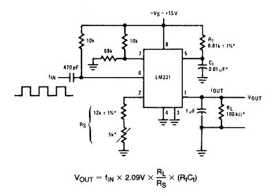
This is Simple Frequency to Vvoltage Converter Circuit Diagram. In these applications, a pulse input at % is differentiated by a C-R network and the negative-going edge at pin 6 causes the input comparator to trigger the timer circuit. Just as with a V-to-F converter, the average current flowing out of pin 1 is IaverAGE = i (1.1 RjC^ f.
In this simple circuit, this current is filtered in the network RL = 100 k ohm and 1 µF. The ripple will be less than 10 mV peak, but the response will be slow, with a 0.1 second time constant, and settling of 0.7 second to 0.1%.
Simple Frequency to Vvoltage Converter Circuit Diagram

Simple Frequency to Vvoltage Converter Circuit Diagram