Showing posts with label tester. Show all posts

Sunday, December 22, 2013

Thyristor Tester

The circuit in the diagram is a very handy tool for rapidly checking all kinds of thyristor (SCR, triac, …). In case of a triac, all four quadrants are tested, which is done with S3, while in case of a standard thyristor, a positive power supply and trigger current need to be set, which is done with S1. The value of resistors R1 and R2 is chosen to obtain a current of about 28mA, which is more than sufficient for most thyristors.

The hold current is determined by R3, and is 125 mA, which is more than adequate to keep the thyristor in conduction after it has been triggered. Since D1 is a red, low-current LED, and D2 a green, low-current LED, it can be seen in a wink in which quadrant the thyristor conducts.

Circuit diagram:

Thyristor Tester Circuit Diagram

Testing is started with S2, and the circuit is reset with S4 after the test has been concluded. Three short lengths of circuit wire terminated into insulated crocodile clips on connector K1 will be found very convenient for linking any kind of thyristor to the circuit. Mind correct connections, though: in the case of a triac, MT1/A1 is linked to earth, the gate to S2 and MT2/A2 to R3; in the case of a standard thyristor, the anode is linked to R3, the cathode to earth, and the gate to S2.

If, in a rare case the trigger current needs to be altered, this can be done by changing the value of resistors R1–R3 as appropriate. The trigger current may also be made variable by the use of a variable power supply. If that is done, make sure that the dissipation in the resistors is not exceeded.
Read More..

Wednesday, September 4, 2013

Simple But Reliable Car Battery Tester

This circuit uses the popular and easy to find LM3914 IC. This IC is very simple to drive, needs no voltage regulators (it has a built in voltage regulator) and can be powered from almost every source. This circuit is very easy to explain: When the test button is pressed, the Car battery voltage is feed into a high impedance voltage divider. His purpose is to divide 12V to 1,25V (or lower values to lower values).

This solution is better than letting the internal voltage regulator set the 12V sample voltage to be feed into the internal voltage divider simply because it cannot regulate 12V when the voltage drops lower (linear regulators only step down). Simply wiring with no adjust, the regulator provides stable 1,25V which is fed into the precision internal resistor cascade to generate sample voltages for the internal comparators. Anyway the default setting let you to measure voltages between 8 and 12V but you can measure even from 0V to 12V setting the offset trimmer to 0 (but i think that under 9 volt your car would not start).

 Car Battery Tester  Circuit diagram:


There is a smoothing capacitor (4700uF 16V) it is used to adsorb EMF noise produced from the ignition coil if you are measuring the battery during the engine working. Diesel engines would not need it, but Im not sure. If you like more a point graph rather than a bar graph simply disconnect pin 9 on the IC (MODE) from power. The calculations are simple (default)
For the first comparator the voltage is : 0,833 V corresponding to 8 V
* * * * * voltage is : 0,875 V corresponding to 8,4 V
for the last comparator the voltage is : 1,25 V corresponding to 12 V
Have fun, learn and dont let you car battery discharge... ;-)

author: Jonathan Filippi
e-mail: jonathan.filippi@virgilio.it
Read More..

Monday, September 2, 2013

Continuity Tester Circuit

Circuit Diagram

Parts
R1 1K
R2 2K2
R3,R4 22K
R5 2K7
R6,R7 56K
R8 *See text
C1,C2 22nF
D1,D2 1N4148
Z1 8V2, 1/4 watt
T1 2N3905 (PNP)
T2,3,4,5 2N3904 (NPN)
9volt Alkaline battery
suitable loudspeaker
housing & probes
An on-off switch is unnecessary. D1 is used when the battery
is brand-new and giving over the nominal 9volt, T1, T2 and T3
acting as the switch for supplying power to the multivibrator.
Design Considerations:
Several simple circuits were tried -- a lamp, battery and probes still demanded the attention of the eyes; replacing the lamp with a buzzer was more successful but needed some three to four volts and gave no indication of a series semiconductor junction if the polarity was correct while the current flow was large enough to damage the more delicate devices within the circuit under test. An extension of the principle to operate an astable (multivibrator) type of oscillator gave good audibility but would operate from zero through to several thousands of ohms and so was too general an indication.
A set of specification was becoming apparent; (1) probe current to be small; (2) probe voltage to be as low as possible, preferable less than 0.3V to avoid seeing germanium or silicon junctions as a continuous circuit; (3) no on/off switch to be used.
The above circuit was the result and several have been designed and are earning their keep for both "heavy" electricians and electronic technicians.

The pcb pattern above is shown full-size at 73mm x 33mm (2-7/8" x 1-1/4")

How it works:
Starting with a 9 volt supply, when the probes are shortcircuited there is a 8.2 volt drop accross the zener diode Z1 leaving a maximum of 0.8 volt across R1. Aplication of Ohms Law shows that a maximum current of 0.8/1,000 = 0.8 mA lows via the probes and this satisfies the first design requirement of low probe current.
T1 is a silicon type and the bse-emitter voltage will need to be about 0.5 to 0.6 volt to forward-bias the junction and initiated collector current. With a maximum of 0.8 volt availabe across R1 it is seen that if a semiconductor junction or resistor is included in the outside circuit under test and drops only 0.3 volt then there will be 0.5 volt remaining across R1, barely enough to bias T1 into conduction.
Assuming that the probes are joined by nearly zero resistance, the pd across R1 is 0.7 - 0.8 volt and T1 turns on, its collector voltage rising positively to give nearly 9 volt across R3. T2 is an emitter follower and its emitter thus rises to about 8.3 volt and this base voltage on T3 (a series regulator circuit or another emitter-follower if you prefer it) results in some 7.7 volt being placed across the T4 - T5 oscillator circuit. All the transistors are silicon types and unless the probes are joined, the only leakage current flows from the battery thus avoiding the need for an On-Off switch. When not in use, the battery in the tester should have a life in excess of a year. My own unit lasted for more than 2 years with one Alkaline battery.
Descriptive Notes:
The output from the speaker is not loud but is more than adequate for the purpose. I used a small transistor radio loudspeaker with an impedance of 25 - 80 Ohms. The resistance should be brought up to 300 ohms by adding series resistor R8. Example, if your speaker is 58 ohms, then R8 = 242 ohms.
An experiment worth doing is to select the value of either C1 or C2 to produce a frequency oscillation that coinsides with the mechanical resonant frequency of the particular loudspeaker in use. Having choosen the right value, which probably lies in the range of 10n - 100n, the tone will be louder and more earpiercing. A "freewheel" diode D2 is connected across the transducer since fast switching sction of the oscillator circuit can produce a surprisingly high back e.m.f. across the coil and these high voltages might other wise lead to transistor damage of breakdown.
Zener diodes do not provide an absolutely constandt volt-drop regardless of current; at the 0.8 mA design current an 8.2 volt diode will quite possibly give only about 8.0 volt drop since test current for zener selection and marking is typically 5 mA or more. A further possible source of error is the battery; the one suggested nominally provides 9V but a brandnew one may be as much as 9.5 to 9.8V until slightly run-down and this "surplus" voltage, combined with an "under-voltage" znere volt-drop will leave considerably more than the forecast voltage available at the probes. A silicon diode D1 is therefore connected in series with the zener to decrease the probe voltage by a further 0.6 volt or so.
During your final testing and before boxing your circuit, the most suitable connection, A or B, is selected for the positive probe wire. The aim is to have the circuit oscillating with short circuited probes but to stop oscillation with the least amount of resistance or the inclusion of a diode (try both ways) between the probes.
No sensitivity control is fitted because I dont think it is worthwhile nor necessary and would spoil the simplicity of the circuit.
There is no easy way to proof the unit against connection to the supply. Be careful if checking AC line wiring and switch off first. In a similar way, if checking electronic apparatus for unwanted bridging between Veroboard tracks, for instance or a suspected crack in a PCB (Printed Circuit Board) track switch off power first also. Good luck!
 Author: Tony van Roon
e-mail:
Source
: http://www.electronics-lab.com
Read More..

Friday, July 12, 2013

Voltage Tester for Model Batteries

With a suitable load, the terminal voltage of a NiCd or lithium-ion battery is proportional to the amount of stored energy. This relationship, which is linear over a wide range, can be used to build a simple battery capacity meter. 

Circuit Image :
 Voltage Tester for Model Batteries Image
Voltage Tester for Model Batteries Circuit Image 

This model battery tester has two functions: it provides a load for the battery, and at the same time it measures the terminal voltage. In addition, both functions can be switched on or off via a model remote-control receiver, to avoid draining the battery when it is not necessary to make a measurement. The load network, which consists of a BC517 Darlington transistor (T2) and load resistor R11 (15 Ω /5 W), is readily evident. When the load is active, the base of T1 lies practically at ground level. Consequently, T1 conducts and allows one of the LEDs to be illuminated. 

Circuit Diagram :
Voltage Tester for Model Batteries-Circuit Diagram
Voltage Tester for Model Batteries Circuit Diagram

The thoroughly familiar voltmeter circuit, which is based on the LM3914 LED driver, determines which LED is lit. The values of R6 and R7 depend on the type and number of cells in the battery. The objective here is not to measure the entire voltage range from 0 V, but rather to display the portion of the range between the fully charged voltage and the fully discharged voltage. Since a total of ten LEDs are used, the display is very precise. For a NiCd battery with four cells, the scale runs from 4.8 V to 5.5 V when R6 = R7 = 2 kΩ. The measurement scale for a lithium-ion battery with two cells ranges from 7.2 V to 8.0 V if R6 = 2 kΩ and R7 = 1 kΩ. 

For remote-control operation, both jumpers should be placed in the upper position (between pin 1 and the middle pin). In this configuration, either a positive or negative signal edge will start the measurement process. A positive edge triggers IC1a, whose output goes High and triggers IC1b. A negative edge has no effect on IC1a, but it triggers IC1b directly. In any case, the load will be activated for the duration of the pulse from monostable IC1b. Use P12 to set the pulse width of IC1a to an adequate value, taking care that it is shorter than the pulse width of IC1b. 

If the voltage tester is fitted into a remote-controlled model, you can replace the jumpers with simple wire bridges. However, if you want to use it for other purposes, such as measuring the amount of charge left in a video camera battery, it is recommended to connect double-throw push-button switches in place of JP1 and JP2. The normally closed contact corresponds to the upper jumper position,while the normally open contact corresponds to the lower position.

Parts :
Resistors:
R1,R2 = 47kΩ
R3 = 100kΩ
R4 = 500kΩ
R5 = 1kΩ
R6,R7 = see text (1% resistors!)
R8 = 1kΩ5
R9 = 1kΩ2
R10 = 330Ω
R11 = 15Ω 5W
R12 = 15kΩ
P1 = 100kΩ preset
Capacitors:
C1 = 10nF
C2 = 100nF
Semiconductors:
D1-D10 = LED, red, high effi-ciency
T1 = BC557
T2 = BC517
IC1 = 74HC123
IC2 = LM3914AN
Miscellaneous:
PC1,PC2,PC3 = solder pin
JP1,JP2 = jumper or pushbutton

PCB Layout :
B. PCB Laout
Voltage Tester for Model Batteries PCB Layout
 
 
Streampowers
Read More..

Monday, May 13, 2013

Quick on board Junction Tester

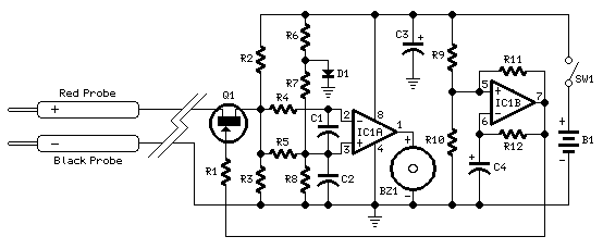
Short circuits or broken pcb tracks can be easily recognized by means of a Multimeter, but this tool can give wrong results when testing the efficiency of a transistor or diode, unless the device under test is unsoldered and removed from the pcb.Junction Tester
Read More..