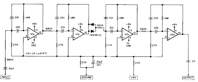
The Razor-sharp CW filter Circuit Diagram consists of four stages of active bandpass filtering provided by two type-µ integrated-circuit dual op amps and includes a simple threshold detector (diodes Dl and D2) between stages 2 and 3 to reduce low-level background noise. Each of the four filter stages acts as a narrow bandpass filter with an audio bandpass centered at 750 Hz. The actual measured 3-dB bandwidth is only 80 Hz wide.
Razor-sharp CW filter Circuit Diagram

No comments:
Post a Comment
Note: Only a member of this blog may post a comment.