Using the RE46C140 circuit can be designed a very simple smoke detector alarm using few external electronic components . The RE46C140 IC is a low power CMOS photoelectric type smoke detector IC that will provide all the required features for a photoelectric type smoke detector project . This smoke detector alarm design incorporates a gain selectable photo amplifier for use with an infrared emitter detector pair. An internal oscillator strobes power to the smoke detection circuitry for 100us every 10 seconds to keep standby current to a minimum. If smoke is sensed the detection rate is increased to verify an alarm condition.
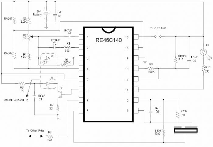
Smoke Detector Alarm Circuit Diagram

An interconnect pin allows multiple detectors to be connected such that when one units alarms, all units will sound. In standby the LED is pulsed on for 10mS every 43 seconds . In a local alarm condition or the push to test alarm the LED pulse frequency is increased to once every 5 seconds. In the case of a remote alarm the LED not active. In the timer mode of operation the LED is pulsed on for 10mS every 10 seconds.
A comparator compares the photo amp output to an internal reference voltage. If the required number of consecutive smoke conditions is met the device will go into local alarm and the horn will be active. The bidirectional IO pin allows interconnection of multiple detectors. In a local alarm condition this pin is driven high immediately through a constant current source. Shorting this output to ground will not cause excessive current. The IO is ignored as an input during a local alarm. This smoke detector circuit must be powered from a 9 volt DC power supply .
Smoke Detector Alarm Circuit Diagram
A comparator compares the photo amp output to an internal reference voltage. If the required number of consecutive smoke conditions is met the device will go into local alarm and the horn will be active. The bidirectional IO pin allows interconnection of multiple detectors. In a local alarm condition this pin is driven high immediately through a constant current source. Shorting this output to ground will not cause excessive current. The IO is ignored as an input during a local alarm. This smoke detector circuit must be powered from a 9 volt DC power supply .
No comments:
Post a Comment
Note: Only a member of this blog may post a comment.