Saturday, August 31, 2013

Simple Operational Amplifier DC Motor Driver

Using a simple operational amplifier and some other common electronic components can be designed a very simple DC motor driver that can be used for a 200mA motor application . Rb sets the bias point for transistors Q1 and Q2.

Because Vbe(ON) varies greatly with temperature, a guardband is required to prevent Q1 and Q2 from conducting simultaneously. RB should be selected such that the transistors do not conduct until lM equals the op amp quiescent supply current, Isy . The transistors will begin to conduct at about Vbe (on) = 0.5V. In this project :
RB= [vbe(on)/(lSY+ Im)]= 0.5/(0.0025 + 0.0025)=100 ohms

To maximize voltage swing across the motor, V1 must be minimized. If at full load V1 = 0.2V with V+ = 15V and VBE1 = 0.8V, the voltage across the motor will be:
VM = (V+ - 2) - VBE1 - V1 = (15 - 2) - 0.8 - 0.2 = 12.0V Vin may be scaled with a resistive divider as:
VIN= (R1 + R2)/R2 With R1 = 240k and R2 = 10k, VIN =5 volt lM = 200mA.
Read More..

Smoke Detector Alarm Using RE46C140

Using the RE46C140 circuit can be designed a very simple smoke detector alarm using few external electronic components . The RE46C140 IC is a low power CMOS photoelectric type smoke detector IC that will provide all the required features for a photoelectric type smoke detector project . This smoke detector alarm design incorporates a gain selectable photo amplifier for use with an infrared emitter detector pair. An internal oscillator strobes power to the smoke detection circuitry for 100us every 10 seconds to keep standby current to a minimum. If smoke is sensed the detection rate is increased to verify an alarm condition.

Smoke Detector Alarm Circuit Diagram


An interconnect pin allows multiple detectors to be connected such that when one units alarms, all units will sound. In standby the LED is pulsed on for 10mS every 43 seconds . In a local alarm condition or the push to test alarm the LED pulse frequency is increased to once every 5 seconds. In the case of a remote alarm the LED not active. In the timer mode of operation the LED is pulsed on for 10mS every 10 seconds.

A comparator compares the photo amp output to an internal reference voltage. If the required number of consecutive smoke conditions is met the device will go into local alarm and the horn will be active. The bidirectional IO pin allows interconnection of multiple detectors. In a local alarm condition this pin is driven high immediately through a constant current source. Shorting this output to ground will not cause excessive current. The IO is ignored as an input during a local alarm. This smoke detector circuit must be powered from a 9 volt DC power supply .
Read More..

ULN2004 Water Level Indicator

This ULN2004 electronic project circuit diagram design is a very simple water level indicator circuit project . This ULN2004 water level indicator circuit is very simple and require few external electronic parts .

ULN2004 is a high voltage, high current darlington arrays that contain seven open collector darlington pairs with common emitters . Each channel rated at 500mA and can withstand peak currents of 600mA.

 ULN2004 Water Level Indicator Circuit Diagram

As the water level rise in the tank , it comes in contact with probes P1 through P7 and thereby makes pins 7 trough 1 high sequentially . The corresponding output pins 10 trough 16 go low one after other and LED1 through LED7 will light up . When water comes in contact with the last probe P7 , the buzzer connected to the last pin 16 will sound .

This electronic circuit project must be powered from a fixed output DC voltage that will provide an output voltage between 9 and 12 volts .
Read More..

TDA7275A DC Speed Controller

Using the TDA7275A linear integrated circuit manufactured in a minidip plastic package can be designed a very simple speed regulator electronic project that can be used for speed regulation of small DC motors .


TDA7275A DC Speed Controller Schematic


TDA7275A DC speed controller project is intended for use as speed regulator for DC motors of record players, tape and cassette recorders. This DC motor speed controller circuit project can provide a maximum output current of 1.5 amperes .

This circuit can be powered with a voltage range between 8 and 18 volts . V2 is typically 1.5 volt for Motor ”Run” (Acc. Following data or open) and 1 volt for Motor ”Stop” (Acc. Following data or grounded) .
Read More..

High Power Alarm Driver

In this circuit, a low-powered SCR is used to trigger a higher powered SCR. When a switch is opening (S2, S3, S4) or closing (S5, S6, S7), either SCR1 or SCR2 triggers. This triggers SCR3 via D1, D2, and R5. BZ1 is a high-powered alarm of the noninterrupting type. 

High-Power Alarm Driver Circuit Diagram


Read More..

Friday, August 30, 2013

Twin T RC Notch Filter

The two T-notch filter can be used to block unwanted frequencies or if placed in an op amp as a bandpass filter. the notch frequency occurs where the capacitive reactance equals the resistance (Xc = R) and if the values are close, the attenuation can be very high and the notch frequency virtually eliminated,Insertion of the filter depends on the load, the output is connected to the subject so that the resistors must be of much lower value than the load for minimal loss.

Twin-T RC Notch Filter Circuit diagram

For audio frequencies, the filter may act as a bass and treble boost circuit by attenuating the midrange. With 1.5K resistors and capacitors 0.1 uF, the band is in stop-10dB 500 Hz to 2 kHz. The depth and breadth of the reaction can be slightly adjusted to a value of 0.5 R and adding some resistance at the C-values,If the circuit is an operational amplifier is used as a bandpass filter, the response should be reduced to avoid oscillation.
Read More..

Friday, August 16, 2013

Diode less Rectifier Circuit Diagram

Diode less Rectifier Circuit Diagram . It`s common knowledge that when working with single-supply op amps, implementing simple functions in a bipolar signal environment can be difficult. Sometimes additional op amps and other electronic components are required. Taking that into consideration, can any advantage be attained from this mode The answer lies in this simple circuit (A). Requiring no diodes, the circuit is a high-precision full-wave rectifier with a liigli-frequency limitation equalling that of the op amps themselves. Look at the circuit`s timing diagram (B) to see the principle of operation. The first amplifier rectifies negative input levels with an inverting gain of 2 and turns positive levels to zero .

The second amp, a noninverting summing amplifier, adds the inverted negative signal from the first amplifier to the original input signal. The net result is the traditional waveform produced by full-wave rectification. In spite of the limitation on the input signal amplitude (it must be less than VCCJZ), this circuit can be useful in a variety of setups.

 Diode less Rectifier Circuit Diagram


Diode less Rectifier Circuit Diagram
Read More..

230V LED

Most of you asked about 230V LED circuit diagrams.Today Im going to introduce you that circuit.I have attached this circuit for my door bell.So that at night I can easily see it.Not only that people can us this circuit to see whether electricity is there or not So use thi9s circuit and get fun....


# Note

# you should be careful when you use this circuit.Because this circuit operates with 230V
# This circuit is not suitable for kids
# When you use electronic parts those parts should have correct values(like W and V)
# Build this circuit on a pcb If the circuit doesnt work dont touch it.Firstly switch off the circuit.
Read More..

Long Delay Stop Switch

Presettable times for train stops in stations are indispensable if you want to operate your model railway more or less realistically according to a timetable. This circuit shows how a 555 timer can be used with a relatively small timing capacitor to generate very long delay times as necessary by using a little trick (scarcely known among model railway electronic technicians): pulsed charging of the timing net-work. Such long delays can be used in hidden yards with through tracks, for instance.  As the timer is designed for half-wave operation, it requires only a single lead to the transformer and one to the switching track or reed contact when used with a Märklin AC system (H0 or H1). The other lead can be connected to any desired grounding point for the common ground of the track and lighting circuits.
Circuit diagram :
Long-Delay Stop Switch-Circuit Diagram
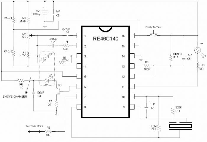
Long-Delay Stop Switch Circuit Diagram

As seen from the outside, the timer acts as a monostable flip-flop. The output (pin 3) is low in the quiescent state. If a negative signal is applied to the trigger input (pin 2), the output goes high and C4 starts charging via R3 and R4. When the voltage on C4 reaches 2/3 of the supply voltage, it discharges via an internal transistor connected to pin 7 to 1/3 of the supply voltage and the output (pin 3) goes low. The two threshold values (1/3 and 2/3) are directly proportional to the supply voltage. The duration of the output signal is independent of the supply voltage: t= 1.1(R4 + R5) × C4 

if the potentiometer is connected directly to the supply line (A and B joined). The maximum delay time that can be generated using the component values shown in the schematic diagram is 4.8 minutes. How-ever, it can be increased by a factor of approximately 10 if the timing network is charged using positive half-waves of the AC supply voltage (reduced to the 10–16-V level) instead of a constant DC voltage. 

The positive half-waves of the AC voltage reach the timing network via D2, the transistor, and D3. Diode D3 prevents C4 from being discharged between the pulses. The total resistance of R4 and R5 should not be too high (no more than 10 MΩ if possible), since electrolytic capacitors (such as are needed for C4) have significant leakage currents. Incidentally, the leakage current of aluminium electrolytic capacitors can be consider-ably reduced by using a supply voltage well below the rated voltage. Capacitor C6 is intended to suppress noise. It forms a filter network in combination with an internal voltage-divider resistor.
If a vehicle happens to remain standing over the reed switch so the magnet holds the contacts constantly closed, the timer will automatically be retriggered when the preset delay times out. In this case the relay armature will not release and the locomotive will come to the ‘end of the line’ in violation of the timetable. This problem can be reliably eliminated using R6, R7 and C5. This trigger circuit ensures that only one trigger pulse is generated, regardless of how long the reed switch remains closed. RC network R8/C7 on the reset pin ensures that the timer behaves properly on switch-on (which is far from being something to be taken for granted with many versions of the 555 or 556 dual timer).
Reed switches have several special characteristics that must be kept in mind when fitting them. The contact blades, which are made from a ferromagnetic material, assume opposite magnetic polarities under the influence of a magnetic field and attract each other. Here the position and orientation of the magnet, the distance between the magnet and the reed switch, and the direction of motion of the magnet relative to the switch are important factors. The fragility of the glass hous-ing and the thermal stress from soldering (stay at least 3 mm away from the glass housing) require a heat sink to be used between the soldering point and the glass/metal seal. A suitable tweezers or flat-jawed pliers can be used for this pur-pose. If you need to bend the leads, use flat-jawed pliers to protect the glass/metal seal against mechanical stresses. 

Matching magnets in various sizes are available from toy merchants and electronics mail-order firms. They should preferably be fitted underneath the loco-motive or carriage. However, the magnet can also be fitted on the side of a vehicle with a plastic body. In this case the reed switch can be hidden in a mast, bridge column or similar structure or placed in a tunnel, since the distance must be kept to less than around 10 mm, even with a strong magnet. If fitting the circuit still presents problems (especially with Märklin Z-gauge Mini-Club), one remedy is to generate the trigger using a unipolar digital Hall switch, such as the Siemens TLE4905L or Allegro UGN3120. To avoid coupled-in interference, the stop timer should be fitted relatively close to the Hall sensor (use screened cable if necessary). Pay attention to the polarity of the magnet when fitting it to the bottom of the vehicle. With both types of sensors, the South pole must point toward the front face of the Hall IC (the face with the type marking). The North pole is sometimes marked by a dab of paint. Generally speaking, the polarity must be determined experimentally. 

Fitting the circuit is not a problem with Z-gauge and 1-gauge tracks, since the distance between the iron parts (rails) and the Hall switch is sufficiently large. In an HO system, some modifications must be made to the track bed of the Märklin metal track. Cut a suitably sized ‘window’ between one wheel rail and the centre rail in order to prevent secondary magnetic circuits from interfering with the operation of the sensor. Keep the distance between the magnet and the case of the Hall switch between 5 and 10 mm, depending on the strength of the magnet, to ensure reliable actuation.


Source by : Streampowers
Read More..

Razor sharp CW filter Circuit Diagram

The Razor-sharp CW filter Circuit Diagram consists of four stages of active bandpass filtering provided by two type-µ integrated-circuit dual op amps and includes a simple threshold detector (diodes Dl and D2) between stages 2 and 3 to reduce low-level background noise. Each of the four filter stages acts as a narrow bandpass filter with an audio bandpass centered at 750 Hz. The actual measured 3-dB bandwidth is only 80 Hz wide.

 Razor-sharp CW filter Circuit Diagram

Razor-sharp CW filter Circuit Diagram

Read More..

Thursday, August 15, 2013

Boat Trailer Partsaccessories Trailer Parts Superstore

Trailer Light Wiring on How To Wire A Trailer With Lights   Brakes   Ehow Com
How To Wire A Trailer With Lights Brakes Ehow Com.


Trailer Light Wiring on Trailer Lights Wiring
Trailer Lights Wiring.


Trailer Light Wiring on 79088 Trailer Lights Wiring Harness Trailer Wiring Bmp
79088 Trailer Lights Wiring Harness Trailer Wiring Bmp.


Trailer Light Wiring on Towing Hitch 12n Socket Wiring Gif
Towing Hitch 12n Socket Wiring Gif.


Trailer Light Wiring on Trailer Wiring Problem   Dodge Diesel   Diesel Truck Resource Forums
Trailer Wiring Problem Dodge Diesel Diesel Truck Resource Forums.


Trailer Light Wiring on The Conector Was Put On Yes Most Trailers Have A Common Wiring Layout
The Conector Was Put On Yes Most Trailers Have A Common Wiring Layout.


Trailer Light Wiring on Axle   Trailer Axles And Running Gear Components   Trailer Plug Wiring
Axle Trailer Axles And Running Gear Components Trailer Plug Wiring.


Trailer Light Wiring on Boat Trailer Parts   Accessories At Trailer Parts Superstore
Boat Trailer Parts Accessories At Trailer Parts Superstore.


Trailer Light Wiring on Sj23 Tech Tip A08   A Guide To Maintain Trailer Lights And Wiring
Sj23 Tech Tip A08 A Guide To Maintain Trailer Lights And Wiring.


Trailer Light Wiring on Trailer Lights Wiring Diagram   Reviews And Photos
Trailer Lights Wiring Diagram Reviews And Photos.


Read More..

Typical Alternator Wiring Diagram Alternator

Alternator Wiring Diagram on Wiring Diagram For Gm Alternators
Wiring Diagram For Gm Alternators.


Alternator Wiring Diagram on Internal Regulator Alternator Testing Guide
Internal Regulator Alternator Testing Guide.


Alternator Wiring Diagram on Wiring 12v Marine Tachometer Diesel Alternator Instructions   How To
Wiring 12v Marine Tachometer Diesel Alternator Instructions How To.


Alternator Wiring Diagram on Delco One Wire Alternator Installation On 5000 Ford Mf135 Wiring Rjs
Delco One Wire Alternator Installation On 5000 Ford Mf135 Wiring Rjs.


Alternator Wiring Diagram on Here S A Wiring Diagram For The Denso Alternator
Here S A Wiring Diagram For The Denso Alternator.


Alternator Wiring Diagram on Typical Alternator Wiring Diagram An Alternator Is A Three
Typical Alternator Wiring Diagram An Alternator Is A Three.


Alternator Wiring Diagram on Westfield World Kitcar Support Site   Wiring A Nippon Denso Alternator
Westfield World Kitcar Support Site Wiring A Nippon Denso Alternator.


Alternator Wiring Diagram on Thread  Auto  Leco S   Help With Some Alternator Wiring Please
Thread Auto Leco S Help With Some Alternator Wiring Please.


Alternator Wiring Diagram on Suggested Wiring Diagram For Alternator Field Disconnect Circuit
Suggested Wiring Diagram For Alternator Field Disconnect Circuit.


Alternator Wiring Diagram on Gm 3 Wire Alternator Idiot Light Hook Up   Hot Rod Forum   Hotrodders
Gm 3 Wire Alternator Idiot Light Hook Up Hot Rod Forum Hotrodders.


Read More..

Circuit modifications for operating 150 LEDs


Parts List

R1 = 220 Ohms, 1/2 watt
R2 = 100Ohms, 2 watts,
RL = All 22 Ohms, 1/4 watt,
C1 = 100uF/25V,
D1,2,3,4,6,7,8 = 1N5408,
D5 = 1N4007
T1 = AD149 or similar,
Transformer = 0-6V, 500mA

Read More..

USB powered battery charger circuit

rangkaian usb untuk charge , mengisi batterei , batteray
At this time I will share about the series used in the usb to charge battery. Issued voltage 4.7 Volt to 5 Volt DC suitable for battery charge the phone, as well as other batteries. 


Below is a circuit where the voltage is removed the usb on the computer will be strengthened by several components so that the voltage used to charge batteries more powerful and filtered, and will make it more durable and long lasting.
USB battery charger schematics
Part List :
R1 = 1 K
R2 = 330 R
R3 = 4K7
R4 = 300 R
R5 = 27R
D1 = 4.7 volt zener /1W
C1 = 100uF/16V
Q1 = BC548
Q2 = BC558A
Read More..

Wednesday, August 14, 2013

Variable High Pass Filter Circuit Diagram

This Variable High-Pass Filter Circuit Diagram second order filter which should prove useful in audio applications uses an LM1458 or other similar of op amp. It is tuneable from 30 to 300 Hz cutoff. R2a, b are ganged log-taper potentiometers. 

Variable High-Pass Filter Circuit Diagram

Variable High-Pass Filter Circuit Diagram

Read More..

100Khz Multiple Output Switching Power Supply Circuit Diagram

The 100Khz Multiple Output Switching Power Supply Circuit Diagram uses two VN4000A 400-V MOSPOWER FETs in a half-bridge power switch configuration. Outputs available are + 5 Vat 20 A and ±15 V (or ±12 V) at 1 A. Since linear three-terminal regulators are used for the low-current outputs, either ±12 V or ±15 V can be made available with a simple change in the transformer secondary windings. 

A TU94 switching regulator IC proVides pulse-width modulation control and drive signals for the power supply. The upper MOSPOWER FET, Q7. in the power switch stage is driven by a simple transformer drive circuit. The lower MOS. Q6, since it is ground referenced. is directly driven from the control !C.

 100Khz Multiple Output Switching Power Supply Circuit Diagram

100Khz Multiple Output Switching Power Supply Circuit Diagram

Read More..

Audio Booster

The amplifiers gain is nominally 20 dB. Its frequency response is determined primarily by the value of just a few components-primarily C1 and R1. The values of the schematic diagram provide a response of ±3.0 dB from about 120 Hz to better than 20,000 Hz.Actually, the frequency response is ruler flat from about 170 Hz to well over 20,000 Hz; its the low end that deviates from a flat frequency response.

The low ends roll-off is primarily a function of capacitor C1(since RIs resistive value is fixed). If C1s value is changed to 0.1 pF, the low ends comer frequency-the frequency at which the low-end roll-off starts-is reduced to about 70 Hz. If you need an even deeper low-end roll-off, change C1 to a 1.0 pF capacitor; if its an electrolytic type, make certain that its installed into the circuit with the correct polarity, with the positive terminal connected to Q1s base terminal
.

Parts:

P1 = 100K
R1 = 47K
R2 = 470K
R3 = 10K
R4 = 560R
R5 = 270R
C1 = 0.1uF-25v
C2 = 3.3uF-25v
C3 = 470uF-25V
D1 = 5mm. Red Led
B1 = 9v Battery
J1 = RCA Audio Input Socket
J2 = RCA Audio Output Socket
S1 = On-Off Switch


Read More..

Constructing your own Dual Power Supply Rise

Many times the hobbyist desires to have a simple, dual power supply for a project. Existing power supplies may be large either in power output or physical size. a simple Dual Power Supply is necessary.For most non-critical applications the best & simplest choice for a voltage regulator is the 3-terminal type.The three terminals are input, ground & output.

The 78xx & 79xx series can provide up to 1A load current & it have on chip circuitry to prevent damage in the event of over heating or excessive current. That is, the chip basically shuts down than blowing out. These regulators are cheap, simple to make use of, & they make it practical to design a method with plenty of P C Bs in which an unregulated supply is brought in & regulation is done locally on each circuit board.

This Dual Power Supply project provides a dual power supply. With the appropriate choice of transformer & 3-terminal voltage regulator pairs you can basically build a tiny power supply delivering up to amp at +/- 5V, +/- 9V, +/- 12V, +/-15V or +/-18V. You require to provide the middle tapped transformer and the 3-terminal pair of regulators you require:7805 & 7905, 7809 & 7909, 7812 & 7912, 7815 & 7915or 7818 & 7918.

The user must pick the pair they needs for his particular application.

Note that the + & - regulators do not must be matched: you can for example, use a +5v & -9V pair. However,the positive regulator must be a 78xx regulator, & the negative a 79xx. They have built in plenty of safety in to this project so it ought to give plenty of years of continuous service.

Transformer
This Dual Power Supply design makes use of a full wave bridge rectifier coupled with a centre-tapped transformer. A transformer with a power output rated at at least 7VA ought to be used. The 7VA rating means that the maximum current which can be delivered without overheating will be around 390mA for the 9V+9V tap; 290mA for the 12V+12V and 230mA for the 15V+15V. If the transformer is rated by output RMS-current then the worth ought to be divided by one.2 to get the current which can be supplied. For example, in this case a 1A RMS can deliver 1/(one.2) or 830mA.

Rectifier
They use an epoxy-packaged four amp bridge rectifier with at least a peak reverse voltage of 200V. (Note the part numbers of bridge rectifiers are not standardised so the number are different from different manufacturers.) For safety the diode voltage rating ought to be at least to times that of the transformers secondary voltage. The current rating of the diodes ought to be two times the maximum load current that will be drawn.

Filter Capacitor
The purpose of the filter capacitor is to smooth out the ripple in the rectified AC voltage. Theres dual amount of ripple is determined by the worth of the filer capacitor: the larger the worth the smaller the ripple.The two,200uF is an appropriate value for all the voltages generated using this project. The other consideration in choosing the correct capacitor is its voltage rating. The working voltage of the capacitor has to be greater than the peak output voltage of the rectifier. For an 18V supply the peak output voltage is one.4 x 18V, or 25V. So they have selected a 35V rated capacitor.

Regulators
The unregulated input voltage must always be higher than the regulators output voltage by at least 3V in order for it to work. If the input/output voltage difference is greater than 3V then the excess potential must be dissipated as heat. Without a heat sink three terminal regulators can dissipate about two watts. A simple calculation of the voltage differential times the current drawn will give the watts to be dissipated. Over two watts a heat sink must be provided. If not then the regulator will automatically turn off if the internal temperature reaches 150oC. For safety it is always best to make use of a small heat sink even in case you do not think you will need.

Stability
C4 & C5 improve the regulators ability to react to sudden changes in load current & to prevent uncontrolled oscillations.

Decoupling
The mono block capacitor C2 & C6 across the output provides high frequency decoupling which keep the impedance low at high frequencies.

LED
Two LEDs are provided to show when the output regulated power is online. You do not must make use of the LEDs in the event you do not require to. However, the LED on the negative side of the circuit does provide a maximum load to the 79xx regulator which they found necessary in the coursework of testing. The negative 3-pin regulators did not like a zero load situation. They have provided a 470R/0.5W resistors as the current limiting resistors for the LEDs.

Diode Protection
These protect chiefly against any back emf which may come back in to the power supply when it supplies power to inductive lots. They also provide additional short circuit protection in the case that the positive output is connected by accident to the negative output. If this happened the usual current limiting shutdown in each regulator may not work as intended. The diodes will short circuit in this case & protect the two regulators.

Dual Power Supply Schematic Diagram


Read More..

Tuesday, August 13, 2013

Car Mobile Phone Charger Circuit

Car Mobile Phone Charger Circuit
Cellphone battery charging process when were done traveling is a big problem. Because when traveling source of power supply is generally difficult to find. If you turn on your phone then the battery continuously over time will run out within a period of five to six hours and eventually mobile phones unusable. Here is described a series of simple charger that will increase battery life two to three hours.


In principle, the charger uses a series of Limited Voltage Current Source. Generally requires cellphone battery voltage 3.6 - 6 volts DC and currents 180-200 mA to perform the charging process. Cellphone battery usually consists of three NiCd battery cells, and each cell has a voltage of 1.2 volts potential. At the speed - average low flows required to charge mobile phone battery about - about 100mA.

Car Mobile Phone Charger Circuit schematics

In this series there is a 12V voltage source consists of 8 regular battery cells (each cell 1.5 Volt) able to supply current at 1.8 A which is connected with output terminals.

The circuit is also able to monitor the battery voltage level which is in charge. And will automatically cut off the charging process when the output terminal detects a certain battery voltage level predetermined. Timer IC NE555 is used to charge and monitor the voltage level in the battery, Pin 5 (IC1) as the control voltage using a reference voltage zener voltage 5.6Volt. Voltage at Pin 6 as the threshold set by VR1 and the voltage at Pin 2 as the trigger is set by VR2.

When the cellphone battery is connected in series (the Charging Process) applied voltage on PIN2 (IC1) as a trigger would be below the value 1 / 3 Vcc and will cause the Flip-Flop in IC1 will ON and on Pin 3 (IC1) will be high (Cause transistor T1 saturation.). When the battery is full (Full Charge) then the voltage will rise and the voltage on the PIN2 (IC1) will be above the level of trigger point threshold. This will cause the Flip Flop OFF and the output will be low (transistor T1 causes the cutoff) and indirectly also the charging process will stop.

Pin 6 (Threshold IC1) is set at 2 / 3 Vcc by using VR1, transistors T1 which is used to increase the charging current. R3 value is very important to provide the charging current, by setting the value of R3 to 39 ohms then the charging current supplied approximately 180mA. This circuit can be built on any type of PCB (General Purpose PCB) for the calibration process using the DC voltage level cutoff Variable Power Supply. Connect the output terminal circuit with Variable DC Power Supply and set on 7 volts. Adjust VR1 in middle position and slowly adjust VR2 until LED1 OFF, this indicates Low Output. LED1 should turn on when the DC Variable Power Supply voltage is reduced below 5V. LED1 Status flame shown in the table below. Closed circuit with plastic casing and use a suitable connector for connecting to the Battery for Mobile.
Read More..

Clean High gain Differential Instrumentation Amplifier

This circuit includes input guarding, cable bootstrapping, and bias current compensation .
Differential bandwidth is reduced by Cl which also makes common-mode rejection less dependent on matching of input amplifiers

 High gain Differential Instrumentation Amplifier


Clean High gain Differential Instrumentation Amplifier
Read More..

10 Watts Mosfet Audio Amplifier

10 Watts Mosfet Audio Amplifier

The diagram shown here is a MOSFET amplifier circuit 10W of sound that only requires a single source. Single railway material rarely used in power amplifiers class-B. However, for low power applications like this is very thin. Actually I have this circuit a old cassette player is still working and republish as it is. The BD512 and BD522 power MOSFETs is obsolete now and you can use any other power MOSFET game instead of them.


Transistors Q1 and Q2 are connected as a Darlington pair works as a preamp. R3 preset controls the quiescent current, while R2 provides. Output is coupled to the speakers through capacitor C4. Capacitor C5 is the power supply filter and C2 is the input DC decoupling capacitor.


Notes.

  • The circuit can be assembled on a vero board.
  • Use 30V DC for powering the circuit.
  • Do not expect much performance from this amplifier.
  • Capacitors C3, C4, C5 must be rated 50V and C2 can be 10V.
  • Use a 8 ohm 15W speaker as load.
Read More..

Structured Wiring

Structured Wiring on Structured Wiring
Structured Wiring.


Structured Wiring on Structured Wiring   Services   Home Audio Video  Home Theater
Structured Wiring Services Home Audio Video Home Theater.


Structured Wiring on Structured Wiring
Structured Wiring.


Structured Wiring on Installs Computer Networking Wiring As Part Of Its Structured Wiring
Installs Computer Networking Wiring As Part Of Its Structured Wiring.


Structured Wiring on Structured Wiring
Structured Wiring.


Structured Wiring on Structured Wiring
Structured Wiring.


Structured Wiring on Structuredwiring Futuresmartpanel Jpg
Structuredwiring Futuresmartpanel Jpg.


Structured Wiring on Structured Wiring
Structured Wiring.


Structured Wiring on Structured Wiring Solution
Structured Wiring Solution.


Structured Wiring on Custom Structured Wiring Panels
Custom Structured Wiring Panels.


Read More..