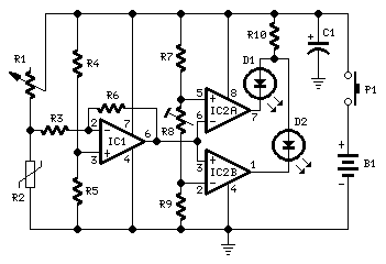
High headroom input circuitry, 9V Battery operation
This circuit is mainly intended to provide common home stereo amplifiers with a microphone input. The battery supply is a good compromise: in this manner the input circuit is free from mains low frequency hum pick-up and connection to the amplifier is more simple, due to the absence of mains cable and power supply. Using a stereo microphone the circuit must be doubled. In this case, two separate level controls are better than a dual-ganged stereo potentiometer. Low current drawing (about 2mA) ensures a long battery life.
Circuit Operation:
The circuit is based on a low noise, high gain two stage PNP and NPN transistor amplifier, using DC negative feedback through R6 to stabilize the working conditions quite precisely. Output level is attenuated by P1 but, at the same time, the stage gain is lowered due to the increased value of R5. This unusual connection of P1, helps in obtaining a high headroom input, allowing to cope with a wide range of input sources (0.2 to 200mV RMS for 1V RMS output).
Portable Microphone Preamplifier Circuit diagram:

P1 = 2.2K
R1 = 100K
R2 = 100K
R3 = 100K
R4 = 8.2K
R5 = 68R
R6 = 6.8K
R7 = 1K
R8 = 1K
R9 = 150R
C1 = 1uF-63V
C2 = 100uF-25V
C3 = 100uF-25V
C4 = 100uF-25V
C5 = 22uF-25V
Q1 = BC560
Q2 = BC550
Notes:
- Harmonic distortion is about 0.1% @ 1V RMS output (all frequencies).
- Maximum input voltage (level control cursor set at maximum) = 25mV RMS
- Maximum input voltage (level control cursor set at center position) = 200mV RMS
- Enclosing the circuit in a metal case is highly recommended.
- Simply connect the output of this device to the Aux input of your amplifier through screened cable and suitable connectors.
Source : http://www.ecircuitslab.com/2011/06/portable-microphone-preamplifier.html