Showing posts with label temperature. Show all posts

Saturday, December 21, 2013

Simple IC LM35 Temperature Sensor Characteristics

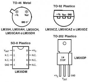
LM 35 temperature sensor IC is a IC chip production Natioanal Semiconductor which serves to determine the temperature of an object or space in the form of electric scale, or can also be defined as an electronic component that is used to change the temperature changes are accepted in the electrical wholesale changes. LM35 temperature sensor IC temperature change can change a change in voltage at the output. LM35 temperature sensor IC requires +5 volts DC source voltage and DC current consumption of 60 mA in operation. Physical form LM 35 temperature sensor is an IC chip with packaging that varies, in general packaging LM35 temperature sensor is packaged TO-92 as shown in the figure below.


Simple IC LM35 Temperature Sensor Characteristics


From the picture above it can be seen that the temperature sensor IC LM35 basically have 3 pin that serves as a source of supply voltage of +5 volts DC, as a result of sensing the output pin in the form of a change in the DC voltage and Vout pin to Ground.

IC LM35 temperature sensor characteristics are:

  •     Temperature sensitivity, with linear scaling factor between voltage and temperature 10 mVolt / º C, so it can be calibrated directly in centigrade.
  •     Have the accuracy or the accuracy of the calibration is 0.5 º C at 25 º C.
  •     Has a maximum operating temperature range between -55 º C to +150 º C. Working at a voltage of 4 to 30 volts.
  •     Has current low at less than 60 mA.
  •     Have a low self-heating (low-heating) of less than 0.1 º C in still air.
  •     Has a low output impedance is 0.1 W for 1 mA load.
  •     have Nonlinearities only about ± ¼ º C.

Read More..

Wednesday, September 4, 2013

High Temperature Detector Using UM3561

This heat detector alarm electronic project is designed using the UM3561 sound generator circuit and some other common electronic parts . This heat detector circuit project uses a complementary pair comprising npn and pnp transistor to detect heat . T3 and T4 transistors connected in darlington configuration are used to amplify the audio signal from the UM3561 ic .

High Temperature Detector Circuit Diagram


When the temperature close to the T1 transistor is hot , the resistance to the emitter –collector goes low and it starts conducting . In same time T2 transistor conducts , because its base is connected to the collector of T1 transistor and the RL1 relay energized and switches on the siren which produce a fire engine alarm sound .
The relay used in this project must be a 6 volt / 100 ohms relay and the speaker must have a 8 ohms load and 1 watt power . This electronic project must be powered from a 6 volts DC, but the UM3561 IC is powered using a 3 volt zener diode , because the alarm sound require a 3 volts dc power supply .
Read More..

Tuesday, September 3, 2013

Temperature Controlled Fan Circuit

Warning! The circuit is connected to 230Vac mains, then some parts in the circuit board are subjected to lethal potential! Avoid touching the circuit when plugged and enclose it in a plastic box.
Description
Gradually increases speed as temperature increases
Widely adjustable temperature range
Circuit Diagram
Parts:
P1 22K Linear Potentiometer (See Notes)
R1 15K @ 20°C n.t.c. Thermistor (See Notes)
R2 100K 1/4W Resistor
R3,R6 10K 1/4W Resistors
R4,R5 22K 1/4W Resistors
R7 100R 1/4W Resistor
R8 470R 1/4W Resistor
R9 33K 4W Resistor
C1 10nF 63V Polyester Capacitor
D1 BZX79C18 18V 500mW Zener Diode
D2 TIC106D 400V 5A SCR
D3-D6 1N4007 1000V 1A Diodes
Q1,Q2 BC327 45V 800mA PNP Transistors
Q2 BC337 45V 800mA NPN Transistor
SK1 Female Mains socket
PL1 Male Mains plug & cable
Device purpose:
This circuit adopt a rather old design technique as its purpose is to vary the speed of a fan related to temperature with a minimum parts counting and avoiding the use of special-purpose ICs, often difficult to obtain.
Circuit operation:
R3-R4 and P1-R1 are wired as a Wheatstone bridge in which R3-R4 generates a fixed two-thirds-supply "reference" voltage, P1-R1 generates a temperature-sensitive "variable" voltage, and Q1 is used as a bridge balance detector.
P1 is adjusted so that the "reference" and "variable" voltages are equal at a temperature just below the required trigger value, and under this condition Q1 Base and Emitter are at equal voltages and Q1 is cut off. When the R1 temperature goes above this "balance" value the P1-R1 voltage falls below the "reference" value, so Q1 becomes forward biased, pulse-charging C1.
This occurs because the whole circuit is supplied by a 100Hz half-wave voltage obtained from mains supply by means of D3-D6 diode bridge without a smoothing capacitor and fixed to 18V by R9 and Zener diode D1. Therefore the 18V supply of the circuit is not true DC but has a rather trapezoidal shape. C1 provides a variable phase-delay pulse-train related to temperature and synchronous with the mains supply "zero voltage" point of each half cycle, thus producing minimal switching RFI from the SCR. Q2 and Q3 form a trigger device, generating a short pulse suitable to drive the SCR.
Notes:
The circuit is designed for 230Vac operation. If your ac mains is rated at about 115V, you can change R9 value to 15K 2W. No other changes are required.
Circuit operation can be reversed, i.e. the fan increases its speed as temperature decreases, by simply transposing R1 and P1 positions. This mode of operation is useful in controlling a hot air flux, e.g. using heaters.
Thermistor value is not critical: I tried also 10K and 22K with good results.
In this circuit, if R1 and Q1 are not mounted in the same environment, the precise trigger points are subject to slight variation with changes in Q1 temperature, due to the temperature dependence of its Base-Emitter junction characteristics. This circuit is thus not suitable for use in precision applications, unless Q1 and R1 operate at equal temperatures.
he temperature / speed-increase ratio can be varied changing C1 value. The lower the C1 value the steeper the temperature / speed-increase ratio curve and vice-versa.
Author: RED Free Circuit Designs
Source: http://www.redcircuits.com
Read More..

Wednesday, July 10, 2013

Wireles Temperature Monitor Has Data Logging Capabilities

You can use a local temperature sensor and an ASK (amplitude-shift-keying) transmitter/receiver pair to design a simple wireless temperature-monitoring system with data-logging capabilities. A microcontroller processes and displays the temperature reading to the user. The microcontroller’s onboard UART (universal asynchronous receiver/transmitter) also allows for data-logging applications.
Wireless Temperature Monitor
 Figure 1. The MaX6577 temperature sensor and 315-MHz MaX1472 aSk transmitter form a wireless temperature-monitoring system.

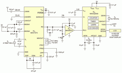
Local-temperature sensor IC1 detects the ambient temperature at the device (Figure 1). The output of IC1 is a square wave with a frequency proportional to temperature in kelvins. ASK transmitter IC2 modulates the signal onto the carrier frequency of 315 MHz. You measure the output signal’s frequency with a frequency counter. The configured scalar multiplier is 1K/Hz when the TS1 pin connects to ground and the TS0 pin connects to VDD. This scalar multiplier is configurable with pins TS1 and TS0. ASK receiver IC3 demodulates the signal at the corresponding carrier frequency (Figure 2).
 
Circuit Diagram
Figure 2. An ASK receiver with a microcontroller processes and displays temperature data.

Comparator IC4 connects to IC3’s RSSI (received-signal-strength indicator) with an internal peak detector. The external RC follows the peak power of the received signal and compares it with a predetermined, resistor-voltage-divider-generated voltage level. Lab experiments show that a threshold of approximately 1.57V generates a valid output on the data-out pin without receiving false readings. Adjust this threshold to the proper level for optimal performance. The comparator’s output is low when the received signal is weak or invalid and high when the received signal is adequate.

Microcontroller IC5 then measures and displays the value of the signal frequency using its integrated timer/counters and LCD-driver peripherals. A counter tracks the number of rising-edge transitions on the input temperature signal, and a timer tracks the elapsed time. After the timer’s 1-sec period elapses, an interrupt occurs. At that moment, the circuit reads the counter value, converts it to Celsius, and displays it on the LCD. The counter then resets to zero to restart the process. The timer automatically reloads once the timer interrupt occurs. UART0 also outputs the resulting temperature. A handheld frequency counter verifies the temperature reading.

The microcontroller monitors the signal power through P6.0, a general-purpose input pin. When the input is logic low, the LCD and UART output “no RF” to alert users of possible transmitter issues when the transmitter and receiver are too far apart from each other. The LCD connection follows the design in the IC’s evaluation kit (Figure 3). Using a look-up table in the data segment of the assembly code enables you to preserve the internal mapping of the display’s A through G segments. This preservation ensures that the display enables the correct segments. Using an RS-232 level converter, the UART output sends data to a data-logging device, such as a computer.

Kit

Figure 3. Maxim MAXQ2000-KIT Evaluation Kit.

Use the MAX-IDE assembler software to program the device during assembly. The MAXQJTAG board operates with the MAX-IDE to load the code onto the device. You can download the project files here. This design provides for a 1-sec temperature-refresh rate in 1°C increments, which is within the accuracy of IC1.

Downloads


Source Code (MAX-IDE assembler software) - download

MAXQ2000-KIT Evaluation Kit user manual and schematic - download
Read More..

Friday, May 17, 2013

Portable Detector Comparator Temperature

Portable Detector Comparator Temperature
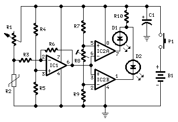
This circuit called the Portable Detector Comparator Temperature, to ascertain actual baby changes in temperature in affiliation to the Ambient temperature.

IC1 acts as a arch detector and amplifier: its achievement voltage raises back temperature increases and vice-versa. This happens because the n.t.c. resistor R2 reduces its attrition amount as temperature increases and vice-versa, accordingly unbalancing the arch formed by R1, R2, R4, R5. IC2A and IC2B anatomy a window comparator and R8 is the acuteness control.

Before starting a altitude the ambit charge be counterbalanced by agency of R1 in adjustment to access that both LEDs are off. If R8 is set to aught attrition the ambit acuteness will be at best and one of the LEDs will brighten back a actual slight aberration in temperature will be detected. As R8 amount is added the ambit acuteness will decrease.

Portable Detector Comparator Temperature Part List

R1 = 22K  Linear Potentiometer
R2 = 15K @ 20°C n.t.c. Thermistor
R3 = 10K
R4,R5,R7,R9 = 22K
R6 = 220K
R8 = 5K
R10 = 680R
C1 = 47µF
D1 = Red LED
D2 = Green LED
IC1 = TL061 Low current BIFET Op-Amp
IC2 = LM393 Dual Voltage Comparator IC
P1 = SPST Pushbutton
B1 = 9V
Read More..

Tuesday, May 14, 2013

Temperature controlled DC fan


Here is a simple circuit based on two transistors that can be used to control the speed of a 12 V DC fan depending on the temperature.A thermistor (R1) is used to sense the temperature. When the temperature increases the base current of Q1 (BC 547) increases which in turn decreases the collector voltage of the same transistor. Since the collector of Q1 is coupled to the base of Q2 (BD 140), the decrease in collector voltage of Q1 forward biases the Q2 more and so do the speed of the motor. Also, the brightness of the LED will be proportional to the speed of the motor.
Read More..