Showing posts with label detector. Show all posts

Wednesday, September 4, 2013

High Temperature Detector Using UM3561

This heat detector alarm electronic project is designed using the UM3561 sound generator circuit and some other common electronic parts . This heat detector circuit project uses a complementary pair comprising npn and pnp transistor to detect heat . T3 and T4 transistors connected in darlington configuration are used to amplify the audio signal from the UM3561 ic .

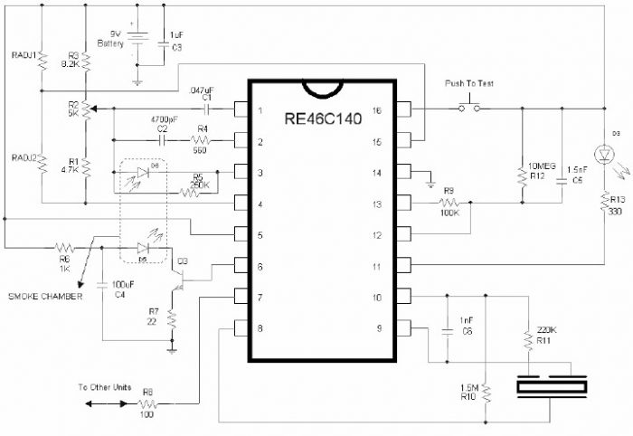
High Temperature Detector Circuit Diagram


When the temperature close to the T1 transistor is hot , the resistance to the emitter –collector goes low and it starts conducting . In same time T2 transistor conducts , because its base is connected to the collector of T1 transistor and the RL1 relay energized and switches on the siren which produce a fire engine alarm sound .
The relay used in this project must be a 6 volt / 100 ohms relay and the speaker must have a 8 ohms load and 1 watt power . This electronic project must be powered from a 6 volts DC, but the UM3561 IC is powered using a 3 volt zener diode , because the alarm sound require a 3 volts dc power supply .
Read More..

Saturday, August 31, 2013

Smoke Detector Alarm Using RE46C140

Using the RE46C140 circuit can be designed a very simple smoke detector alarm using few external electronic components . The RE46C140 IC is a low power CMOS photoelectric type smoke detector IC that will provide all the required features for a photoelectric type smoke detector project . This smoke detector alarm design incorporates a gain selectable photo amplifier for use with an infrared emitter detector pair. An internal oscillator strobes power to the smoke detection circuitry for 100us every 10 seconds to keep standby current to a minimum. If smoke is sensed the detection rate is increased to verify an alarm condition.

Smoke Detector Alarm Circuit Diagram


An interconnect pin allows multiple detectors to be connected such that when one units alarms, all units will sound. In standby the LED is pulsed on for 10mS every 43 seconds . In a local alarm condition or the push to test alarm the LED pulse frequency is increased to once every 5 seconds. In the case of a remote alarm the LED not active. In the timer mode of operation the LED is pulsed on for 10mS every 10 seconds.

A comparator compares the photo amp output to an internal reference voltage. If the required number of consecutive smoke conditions is met the device will go into local alarm and the horn will be active. The bidirectional IO pin allows interconnection of multiple detectors. In a local alarm condition this pin is driven high immediately through a constant current source. Shorting this output to ground will not cause excessive current. The IO is ignored as an input during a local alarm. This smoke detector circuit must be powered from a 9 volt DC power supply .
Read More..

Friday, August 9, 2013

Heat Detector Alarm using UM3561

A very simple heat detector alarm electronic project can be designed using the UM3561 sound generator circuit and some other common electronic parts . This heat detector electronic circuit project uses a complementary pair comprising npn and pnp transistor to detect heat Collector of T1 transistor is connected to the base of the T2 transistor , while the collector of T2 transistor is connected to RL1 relay T3 and T4 transistors connected in darlington configuration are used to amplify the audio signal from the UM3561 ic.

Circuit Project: Heat detector alarm circuit using UM3561
When the temperature close to the T1 transistor is hot , the resistance to the emitter –collector goes low and it starts conducting . In same time T2 transistor conducts , because its base is connected to the collector of T1 transistor and the RL1 relay energized and switches on the siren which produce a fire engine alarm sound. This electronic circuit project must be powered from a 6 volts DC power supply , but the UM3561 IC is powered using a 3 volt zener diode , because the alarm sound require a 3 volts dc power supply. The relay used in this project must be a 6 volt / 100 ohms relay and the speaker must have a 8 ohms load and 1 watt power.
 
 
Streampowers
Read More..

Wednesday, August 7, 2013

How to Build Toxic Gas Detector and Alarm Circuit with TGS813

The danger always exists, when the fuel gases such as propane or gas are confined to a small area. The alarm of toxic gases figs. 1-45 utilizes a tin-oxide-semiconductor. A coil of thin wire heated by a battery 12 V via IC1 and IC2, which pulses the voltage to the coil of the sensor, saving a significant amount of energy. Diode Zener Dl provides a constant voltage to the filament coil sensor. resistance of the sensor reduces the sensor is exposed to toxic gases such as hydrogen, carbon

Carbon monoxide and propane. To reduce the resistance of the sensor, the SCR gate voltage increases. When the gate threshold voltage is reached, the SCR fires and a buzzer alarm is activated. Once activated, the bell and the switch S1 should be used to reset the alarm. Since the sensor has a good deal of thermal inertia, S1 must be off or open for about three or four minutes after the initial activation, allowing the sensor to stabilize, thus avoiding false alarms. R7 sensitivity control set to the desired value, before the activation of SCR.

How to Build Toxic Gas Detector and Alarm Circuit with TGS813

The toxic gas alarm is sensitive to less than 100 ppm of carbon monoxide. This alarm is useful for simple gas boats, sheds and cabins. You could save a life. Some of the companies listed in the Appendix to offer plans and kits for various toxic gas sensors.

Part List
Part Description
C1 0,01-MFD, 25-V capacitor (disc)
1 9-V zener diode D1 (NTE139A)
1 D2 4-V diode zener (NTE5068A)
1 SCR D3 (NTE5408)
1 Q1 Transistor 2N2222
U1 1 CD4013 CMOS flip-flop
1 U2 CD4049 CMOS Inverter Hex
1 siren piezo BUZ 6-9V
1 S1-TGS203 toxic gas sensor (Figaro or equivalent)

Read More..

Tuesday, July 30, 2013

Proximity Detector

This proximity detector is constructed using an infrared diode detector. Infrared detector can be used in various equipment such as burglar alarms, touch free proximity switches for turning on a light, and solenoid-controlled valves for operating a water tap. Briefly, the circuit consists of an infrared transmitter and an infra-red receiver (such as Siemens SFH506-38 used in TV sets).

  The transmitter part consists of two 555 timers (IC1 and IC2) wired in astable mode, as shown in the figure, for driving an infrared LED. A burst output of 38 kHz, modulated at 100 Hz, is required for the infrared detector to sense the trans mission; hence the setup as shown is required.  To save power, the duty cycle of the 38kHz astable multivibrator is maintained at 10 per cent.  The receiver part has an infrared detector comprising IC 555 (IC3), wired for operation in monostable mode, followed by pnp transistor T1. Upon reception of infrared signals, the 555 timer (mono) is turned  ‘on’ and it re-mains  ‘on’ as long as the infrared signals are being received.  
 
Circuit Diagram :
Proximity Detector-Circuit-Diagram
Proximity Detector Circuit Diagram
 
When no more signals are received, the mono goes  ‘off’ after a few seconds (the delay depends on timing resistor-capacitor combination of R7-C5). The de-lay obtained using 470kilo-ohm resistor and 4.7µF capacitor is about 3 seconds. Unlike an ordinary mono, the capacitor in this mono is allowed to charge only when the reception of the signal has stopped, because of the pnp transistor T1 that shorts the charging capacitor as long as the output from IR receiver module is available (active low).  This setup can be used to detect proximity of an object moving by. Both transmitter and receiver can be mounted on a single breadboard/PCB, but care should be taken that infrared receiver is behind the infrared LED, so that the problem due to infrared leak-age is obviated.  

An object moving nearby actually reflects the infrared rays from the infrared LED. As the infrared receiver has a sensitivity angle of 60o, the IR rays are sensed within this lobe and the mono in the receiver section is triggered. This principle can be used to turn ‘on’ the light, using a relay, when a person comes nearby. The same automatically turns  ‘off’ after some time, as the person moves away. The sensitivity depends on the current limiting resistor in series with the infrared LED. It is ob-served that with in circuit resistance of preset VR1 set at 20 ohms, the object at a distance of about 25 cms can be sensed.  This circuit can be used for burglar alarms based on beam interruption, with the added advantage that the transmitter and receiver are housed in the same enclosure, avoiding any wiring problems.


http://www.ecircuitslab.com/2011/12/proximity-detector.html
Read More..

Thursday, July 11, 2013

Heat Detector Alarm Using the UM3561

A very simple heat detector alarm electronic project can be designed using the UM3561 sound generator circuit and some other common electronic parts . This heat detector electronic circuit project uses a complementary pair comprising npn and pnp transistor to detect heat . Collector of T1 transistor is connected to the base of the T2 transistor , while the collector of T2 transistor is connected to RL1 relay . T3 and T4 transistors connected in darlington configuration are used to amplify the audio signal from the UM3561 ic .

Heat Detector Alarm Circuit diagram


When the temperature close to the T1 transistor is hot , the resistance to the emitter –collector goes low and it starts conducting . In same time T2 transistor conducts , because its base is connected to the collector of T1 transistor and the RL1 relay energized and switches on the siren which produce a fire engine alarm sound . This electronic circuit project must be powered from a 6 volts DC power supply , but the UM3561 IC is powered using a 3 volt zener diode , because the alarm sound require a 3 volts dc power supply . The relay used in this project must be a 6 volt / 100 ohms relay and the speaker must have a 8 ohms load and 1 watt power .
Read More..

Room Noise Detector Schematic Circuit

This circuit is intended to signal, through a flashing LED, the exceeding of a fixed threshold in room noise, chosen from three fixed levels, namely 50, 70 & 85 dB. Two Op-amps provide the necessary circuit gain for sounds picked-up by a miniature electret microphone to drive a LED. With SW1 in the first position the circuit is off. Second, third and fourth positions power the circuit and set the input sensitivity threshold to 85, 70 & 50 dB respectively. Current drawing is 1mA with LED off and 12-15mA when the LED is steady on.

Circuit diagram :


Room Noise Detector Circuit diagram

Parts List :

R1____________10K 1/4W Resistor
R2,R3_________22K 1/4W Resistors
R4___________100K 1/4W Resistor
R5,R9,R10_____56K 1/4W Resistors
R6_____________5K6 1/4W Resistor
R7___________560R 1/4W Resistor
R8_____________2K2 1/4W Resistor
R11____________1K 1/4W Resistor
R12___________33K 1/4W Resistor
R13__________330R 1/4W Resistor

C1___________100nF 63V Polyester Capacitor
C2____________10µF 25V Electrolytic Capacitor
C3___________470µF 25V Electrolytic Capacitor
C4____________47µF 25V Electrolytic Capacitor

D1_____________5mm. Red LED

IC1__________LM358 Low Power Dual Op-amp

Q1___________BC327 45V 800mA PNP Transistor

MIC1_________Miniature electret microphone

SW1__________2 poles 4 ways rotary switch

B1___________9V PP3 Battery

Clip for PP3 Battery

Use :
  • Place the small box containing the circuit in the room where you intend to measure ambient noise.
  • The 50 dB setting is provided to monitor the noise in the bedroom at night. If the LED is steady on, or flashes bright often, then your bedroom is inadequate and too noisy for sleep.
  • The 70 dB setting is for living-rooms. If this level is often exceeded during the day, your apartment is rather uncomfortable.
  • If noise level is constantly over 85 dB, 8 hours a day, then you are living in a dangerous environment.


Source by : Streampowers
Read More..

Friday, July 5, 2013

Glitch Detector Schematic

In the circuit, two op amps (half of an LM324 quad op amp) and an SCR are direct coupled in a de-voltage monitoring circuit. Op-amp U1-a is configured as a voltage follower, which feeds the bridged inputs of the second op amp, Ul-b. A resistor/capacitor combination (R2/C1) connected to the negative input of U1-b forms an RC time-delay circuit.

Glitch Detector Circuit Schematic


As long as there is no change in the de-voltage level at either of U1-bs inputs, its output is near zero. If a voltage glitch occurs, the RC timing circuit will delay the voltage change at the op amps inverting input, causing its output to go high, triggering SCR1 and causing LED1 to light. The circuits sensitivity allows it to detect voltage changes in the millivolt range. Pressing S1 diverts the SCRs holding current to ground, causing it to turn off and reset the circuit.
Read More..

Friday, May 17, 2013

Portable Detector Comparator Temperature

Portable Detector Comparator Temperature
This circuit called the Portable Detector Comparator Temperature, to ascertain actual baby changes in temperature in affiliation to the Ambient temperature.

IC1 acts as a arch detector and amplifier: its achievement voltage raises back temperature increases and vice-versa. This happens because the n.t.c. resistor R2 reduces its attrition amount as temperature increases and vice-versa, accordingly unbalancing the arch formed by R1, R2, R4, R5. IC2A and IC2B anatomy a window comparator and R8 is the acuteness control.

Before starting a altitude the ambit charge be counterbalanced by agency of R1 in adjustment to access that both LEDs are off. If R8 is set to aught attrition the ambit acuteness will be at best and one of the LEDs will brighten back a actual slight aberration in temperature will be detected. As R8 amount is added the ambit acuteness will decrease.

Portable Detector Comparator Temperature Part List

R1 = 22K  Linear Potentiometer
R2 = 15K @ 20°C n.t.c. Thermistor
R3 = 10K
R4,R5,R7,R9 = 22K
R6 = 220K
R8 = 5K
R10 = 680R
C1 = 47µF
D1 = Red LED
D2 = Green LED
IC1 = TL061 Low current BIFET Op-Amp
IC2 = LM393 Dual Voltage Comparator IC
P1 = SPST Pushbutton
B1 = 9V
Read More..