Friday, December 20, 2013

Automatic Water Level Controller

Water-level controllers are common nowadays. The one described here is built around timer NE555 and inverter buffer CMOS IC CD4049. It uses readily-available, low-cost components, and is easy to build and install on the over-head tank (OHT) to prevent wastage of water. The circuit works off a 12V battery or 230V AC mains using a 12V adaptor. The three sensors built from non-corrosive metal are fitted to the OHT as shown in Fig. 2 and connected to the circuit (Fig. 1) at appropriate terminals.

Automatic Water-Level Controller Circuit Diagram

Power supply terminal Vcc is at the bottom of the tank, sensor terminal L is just above the bottom of the tank and sensor terminal H is at the top of the tank. After you have properly installed the sensors in the OHT and connected the power supply, the circuit is ready to use. Since Vcc terminal is at the bottom of the tank, when the water level falls below sensor L, timer IC2 is triggered at pin 2 via inverters N1 and N2 and its output goes high. As a result, the output of timer IC2 goes high. Relay RL1 energises and the motor starts filling water in the tank.

Automatic Water-Level Controller Circuit Diagram
Automatic Water-Level Controller

The motor remains ‘on’ even when the water level crosses sensor L. As water in the tank rises to touch sensor H, timer IC2 is retriggered at pin 6 via inverters N3 and N4 and as a result, its output goes low. The relay de-energises and the motor stops filling water in the tank. The motor remains ‘off’ even when the water level falls below sensor H. As water is consumed and its level falls below sensor L, the motor restarts. Thereafter, the cycle repeats. You can also manually start and stop the motor using switch S1.

Read More..

Thunderstorm Predictor

Sure, listening to VHF FM has great advantages over MW/LW AM from the old days — now we have bright stereo free from interference, fading and noise! However, your FM radio will no longer predict the arrival of a thunderstorm as did the AM radio many years ago-reliably and hours before the trouble was upon you!

The crux is that AM detection will faithfully reproduce the effects of lightning and other massive static discharges approaching in a very simple way: they’re audible as slight crackling noises in the loudspeaker, almost irrespective of the tuning of the radio! Assuming no AM radio is available anymore, a dedicated VLF receiver tuned to about 300 kHz can faithfully detect the crackle of approaching lightning.

The simple receiver shown here consists of a loosely tuned amplifier driving a kind of flasher circuit that blinks an LED in synchronicity with the lightning bolts. The frequency and intensity of the LED activity indicates the intensity and distance of the storm respectively. Looking at the circuit diagram, the LED driver is not biased to flash until a burst of RF energy, amplified by T1, arrives at the base of T2.
Thunderstorm Predictor Circuit Diagram

The receiver works off 3 volts and has a negligible standby current of about 350 microamperes which will hardly dent the shelf life of a couple of 1.5-V D-size cells. T2 and T3 form a monostable generator triggered by sudden drops in T1’s collector voltage. Preset P1 is adjusted until the LED remains off when you’re sure there’s no thunderstorm around for a few hundred miles. The value of the LED series resistor is subject to experimentation and LED current.

L2, C1 and the antenna are coarsely tuned for resonance at about 300 kHz. Frequency-wise, lightning is a fairly broadband phenomenon so any tuning to between 200 and 400 kHz will be fine for the circuit but make sure you’re not accidentally tuned to a nearby VLF transmitter! The input signal is obtained from a 70-cm long piece of stiff wire, with coil L1 inserted for impedance matching and lengthening the antenna electrically.

Warning:
This circuit and in particular the antenna must not be used to attract lightning. Consequently, neither the circuit nor the antenna may be used outdoors and/or powered from the mains.
Author: Karel Walraven - Copyright: Elektor Electronics
Read More..

Super Ni Cd Battery Charger 12 18V Circuit Diagram

A clever charger circuit that safely can charge any Ni-Cd battery. Offers charge current sellection, polarization detection and protection and the ability to connect many batterys in siries. Ni-Cd bateries can be recharged more than 1000 times before become useless. the charging current shoud be the 1/10 of the (Ah) of the battery. The bateries need 14 hours to be fully charged.Swhitch S2 is the current selection as folows: 50mA, 200mA and 400mA. LED D10 is the indicator for proper batery connection and/or wrong polarity checking. LED D9 is the charging indicator. The transformer is a 220V/2x12V 0.5A. 

Super Ni-Cd Battery Charger 12-18V Circuit Diagram


Super Ni-Cd Battery Charger 12-18V Circuit Diagram


 PARTS LIST
R1,R4,R5=10K 
R2,R3=100K 
R6,R8,R10=1K 
R7=820 
R9=100 
R11=15 
R12=3,9 
R13=1,8 
C1=1000uF/40v 
C2=470pf 
D1-D4,D6=1n4001-7 D7,D8=1n4148 
D9,D10=LED IC=741 
TR1=BC548 
TR2=BD137 
TR3=2N3055

Datasheet file1: Click here to download LM741.pdf datasheet.
Datasheet file2: Click here to download BC548.pdf datasheet.
Datasheet file3: Click here to download BD137.pdf datasheet.
Datasheet file4: Click here to download 2N3055.pdf datasheet.

Read More..

Build a Photomultiplier Circuit Diagram

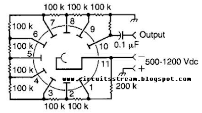
How to Build a Photomultiplier Circuit Diagram? This Photomultiplier Circuit Diagram is typical of the way that a photomultiplier tube is used. The circuit shown is ac coupled, but if dc coupling is needed, the capacitor can be omitted and a suitable interfacing method used. A typical tube is the widely available 931/931A.

Photomultiplier Circuit Diagram

Photomultiplier Circuit Diagram

Read More..

Shortwave SW Transmitter Based IC BEL1895


Here the SW transmitter circuit based on IC BEL1895. This particular transmitter circuit works in shortwave HF band (6 MHz to 15 MHz), and can be applied for shortrange communication and for educational purposes.

Shortwave (SW) Transmitter Circuit diagram :


The circuit is composed of a mic amplifier circuit, a variable frequency oscillator, and modulation amplifier stages. Transistor T1 (BF195) is put to use as a simple RF oscillator. Resistors R6 and R7 determine base bias, while resistor R9 is utilized for stability. Feedback is provided by 150pF capacitor C11 to maintain oscillations. The primary of shortwave oscillator coil and variable condenser VC1 (365pF, 1/2J gang) form the frequency determining network.

By altering the coil inductance or the capacitance of gang condenser, the frequency of oscillation can be modified. The carrier RF signal from the oscillator is inductively coupled through the secondary of transformer X1 to the next RF amplifier-cum-modulation stage assembled around transistor T2 that is run in class ‘A’ mode. Audio signal from the audio amplifier assembled around IC BEL1895 is coupled to the emitter of transistor 2N2222 (T2) for RF modulation.

IC BEL1895 is a monolithic audio power amplifier intendeded for sensitive AM radio applications. It can deliver 1W power to 4 ohms at 9V power supply, with low distortion and noise characteristics. Since the amplifier’s voltage gain is of the order of 600, the signal from condenser mic can be straightly linked to its input without any amplification.

The transmitter’s stability is managed by the quality of the tuned circuit parts as well as the degree of regulation of the supply voltage. A 9V regulated power source is required. RF output to the aerial consists of harmonics, because transistor T2 doesn’t have tuned coil in its collector circuit. However, for short-range communication, it does not create any trouble. The harmonic content of the output may be lowered by means of a high-Q L-C filter or resonant L-C traps tuned to each of the prominent harmonics. The power output of this transmitter is about 100 milliwatts.
Read More..

Thursday, December 19, 2013

Lead Acid Battery Protector

The circuit described here can be used to  ensure  that  a  12 V  sealed  lead  acid  (SLA)  gel battery isn’t discharged too deeply. The  principal part of the circuit is a bistable relay,  which is driven by the output of an op amp.

Lead Acid Battery Protector Circuit Diagram
Lead Acid Battery Protector dd

The battery voltage is first reduced via D1, R1,  P1 and R2, and then continuously compared  with a reference voltage set up by diode D2.  When the battery discharges too much and  its terminal voltage drops below the level  set by P1, the output of the opamp becomes  High, which causes the relay to toggle. This  in turn isolates the load from the battery. The  battery can be reconnected via S1 once the  battery has been replaced or recharged.

The relay used in the prototype is a 5 V bistable type made by Omron (G6AK-234P-ST-US  5 VDC). The two windings of the relay each  have a resistance of 139 Ω (for the RAL-D 5  W-K made by Fujitsu this is 167 Ω). When the  battery voltage starts to become too low and  the relay is being reset the current consumption of the circuit is about 45 mA. Shortly  after the load has been disconnected, when the battery voltage rises above the reference  voltage again, the reset coil will no longer be  powered and the current consumption drops  back to about 2.5 mA.

The range of P1 has intentionally been kept  small. With a reference voltage of 5.6 V (D2)  and a voltage drop of 0.64 V across D1, the circuit reacts within a voltage span of 11.5 V and  11.8 V. This range is obviously dependent on the zener diode used and the tolerance.

For a greater span you can use a larger value  for P1 without any problems. With the potentiometer at its mid setting the circuit switches  at about 11.6 V.

source : http://www.ecircuitslab.com/2012/05/lead-acid-battery-protector.html
Read More..

Mini Running Text Display

This charming little circuit is a genuine four-digit running-text display, complete with a Christmas / New Year’s greeting. Naturally, any competent programmer can easily arrange to have a different text scroll across the display. The associated soft-ware, including the source code, can be downloaded from the Free Downloads section of our website or obtained from Readers Services on diskette (order number 020365-11).

Mini Running Text Display Circuit Image :
 Simple Mini Running Text Display-Image

As can be seen from the schematic, the hardware consists of little more than an AT90S1200 microcontroller, a 4-digit LED display and a 5-V voltage regulator. The only external circuitry needed by the microcontroller consists of a reset circuit and a 4-MHz crystal, and the remainder of the components are limited to a few decoupling capacitors.

Mini Running Text Display Circuit diagram : 

Simple Mini Running Text Display-Circuit Daigram

In the prototype model, an Osram SLO2016 display module was used. Although this four-digit module measures only 10×20 mm, it provides an especially clear and bright display. In order to give the 7805 voltage regulator sufficient ‘breathing room’, the supply voltage should be at least 8 V. A standard 9-V mains adapter should thus be perfectly adequate. The supply voltage does not have to be stabilised, and the adapter does not have to provide an especially large amount of current, since the running-text display draws scarcely more than 50 mA.


Read More..