Friday, December 27, 2013

Build a PIC Security System Dials Your Cell Phone Circuit Diagram

This is a simple PIC Security System Dials Your Cell Phone Circuit Diagram. Do-it-yourself phone dialer security system calls your cell phone, office etc. whenever a door or window is opened, or panic button is pressed. Great Home Alarm.

PIC Security System Dials Your Cell Phone Circuit Diagram

PIC Security System Dials Your Cell Phone Circuit Diagram


The circuit consists of a small PIC microcontroller, assembly program, and a few other parts to detect a switch closure from an open door, window, or manual push button and then dial the cell phone number, and transmit a steady tone to indicate the source of the call. The circuit uses the pulse dialing system to interrupt the line connection a number of times to indicate each digit. Pulse dialing (the oldest form of dialing) works by actually disconnecting or "hanging up" the phone line a number of times to indicate each digit. For example, the digit "5" would be dialed by disconnecting and reconnecting the line 5 times in short intervals of about 100mS. There is about a 1 second pause (with the line connected) between each digit. The timing is not critical and I was able to dial 411 and connect to the local information service just using a momentary push button switch in series with the phone line.

Circuit Operation:
In operation, the switch closure is detected on pin 7 of the processor which activates the reed relay and takes the line off-hook for 3 seconds to establish the dial tone. The processor then dials the number by opening and closing the relay a number of times for each digit. When dialing is complete, the processor waits 3 seconds and then transmits a steady tone of about 300Hz for 30 seconds through the modem transformer. The call is then terminated and the processor waits for the switch to open before resetting.

Design Considerations:

The PIC16F628 (18 pin) processor was selected because I had a few on hand and my homemade hardware programmer only accepts 18 pin devices. A smaller 8 pin device could have been used since only three I/O lines are needed, but the difference in cost is only about $1.50. One of the I/O lines (RA5) is used for programming and is always an input, but can used as a functional input so the switch closure could be detected on this line thus eliminating the need for one pullup resistor. But I elected to use 3 consecutive I/O pins (7,8,9) of the 8 bit port B and leave RA5 pulled up with a extra 10K resistor.

The output pins (8,9) that drive the relay and transformer are limited to 25mA of current each, so an extra transistor (2N2222A) was needed to supply additional current to the relay coil. The transformer resistance is around 100 ohms, so an additional 330 ohm resistor was added in series with pin 9 to limit the transformer current to around 10mA. An LED indicator and 330 ohm resistor were used on pin 8 to observe the dialing activity and indicate the line status. Several of the parts (relay, transformer and blocking capacitor) were obtained from an old 56K modem card.

The schematic shows a 47uF / 50 volt non-polarized capacitor used to block DC current to the transformer, however a regular polarized 50uF cap could be used if correct phone line polarity is observed. The modem was probably designed to work with unknown polarities at different locations, so a non-polarized cap was used. Its possible the cap and 470 ohm resistor can be replaced with a single resistor in series with the line to set the "off hook" line current to around 20mA. This may cause partial saturation of the transformer and reduced audio level, but might work well enough.

The power supply voltage is not critical and a 4.5 volt supply from three AA batteries should work. Or a switching type regulated 5 volt wall transformer can be used. The problem is insuring the relay gets enough voltage to operate. The rest of the circuit should run on reduced voltage. I used a 4.2 volt cell phone charger that worked well.

 Softwre
Read More..

cell phone jammer can be used in many different locations

cell phone jammer can be used in many different locations.
Gome relevant responsible person said, 3C products as the countrys largest retail outlets, Gome will continue to play a channel edge, constantly driving down the price of smart phones, and promote the rapid popularization of smart phones to achieve. The above is a brief analysis of the entire smart phone market in 2011 and the subsequent trend, in fact, the contents of the trend report, we generally can be drawn about the several conclusions: the future of the smart phone market in the short term there will be a flowers dispute put state; 2, smart phones in terms of functionality, integration and user-friendly development will eventually lead to the complete detachment of the interdependence between smartphones and traditional PCs. Of course, for the different locations, different kinds of cell phone jammer are required.
The role played by traditional 3C stores in the future smartphone sales will be increasing; the future of smart phones is the mobile phone development. Survey of Chinese mobile phone. 2008 Marketing Professional of the Yuzhong District Teaching Department. Abstract: From 1998, China formally enter the mobile phone production date from 2003, won the big half of the peak in 2004, falling about 30% of the market share, now clinging to the way bittersweet, domestic mobile phone. In a few short years, China has become the worlds largest mobile phone users. Process along the way, the domestic mobile phone encountered a setback, but also saw the opportunity. In this paper, and international brand mobile phone competition in the domestic mobile phone to find the advantage of domestic mobile phone, also found that the challenges and opportunities to come. cell phone jammer can own different indices and parameters.
According to statistics, in 1996 made the first GSM mobile phone available, starting later than the foreign brands a decade, from the development point of view of the market share of domestic brands is almost zero in 1997, officially started in 1998, 1999 13 million units, accounting for 5% of the national production; 2000, 4.4 million, accounting for 6.4%; 10.48 million in 2001, accounting for 12.3%; has been a breakthrough fierce fighting in 2002 reached 14.97 million per month from 1-10 sales of 14.45 million, of which exports 330,000, accounted for 19.8 percent of the national total production in the domestic market share has reached 33 percent, an increase of 11 percentage points over the same period last year. cell phone jammer should have different performances and functions.
To the four indicators, the product quality of the phone (referred to as quality), the appearance of the product of the mobile phone (referred to as appearance), the price of the phone (referred to as price), and mobile phone products (referred to as functions) for the investigation of an index, and the quality, appearance , functional three-level indicators are divided into a number of secondary indicators.
Read More..

Thursday, December 26, 2013

Telephone Tapping Indicator

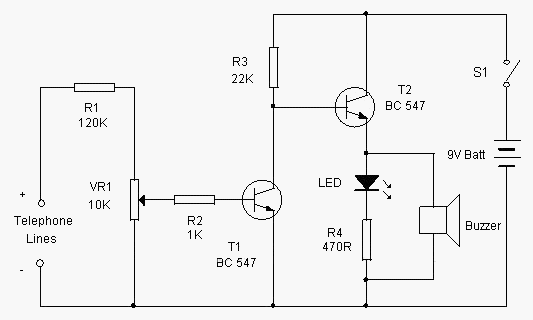
This simple circuit can indicate a misuse or tapping of Telephone line through a loud alarm. The circuit is too simple and can be easily assembled on a common PCB. Line voltage of Telephone lines is around 48 volts DC in the On hook state. When the handset is lifted, this voltage reduces to 12 volt DC. This change in voltage level is used to activate the circuit.When the switch S1 is closed, circuit becomes active and the telephone enters into the armed state.

The high volt DC from the telephone line passes through R1 and VR1 and bias T1 into conduction. As a result, the collector of T1 goes to ground potential to inhibit T2 from conduction. Buzzer and LED thus remain off. When the handset is lifted, the DC voltage from the telephone lines drops to 12 volts. This turns off T1 and T2 conducts. Buzzer beeps and LED lights indicating that the telephone is using.

Telephone Tapping Indicator Circuit

Circuit Project: Telephone Tapping Indicator

Setting
Connect the circuit to Telephone lines using a telephone plug. The free socket of the telephone or Caller ID can be used. Close S1 and adjust VR1 till buzzer stops beeping. Lift the handset. Buzzer should sound. Otherwise, just adjust VR1 till buzzer beeps.
Read More..

mobile phone jammer is installed in the hallway of every floor

 mobile phone jammer is installed in the hallway of every floor.
Sun at age 16 moved to the United States, California, and the learning of the University of California at Berkeley, majoring in Economics. School, where he invented a pocket translator, and applied for a patent, after the price of one million U.S. dollars, to sell translator Sharp company. Later created the Unison, the company is now for all Kyocera. Sun back to the Japanese banking software company, founded in 1981, the goal is to popularize computer knowledge to the Japanese. Early development of the Internet, Sun to his unique vision and courage to invest a large number of successful Internet startups including Yhaoo, ETrade, Softbank deservedly stood in the forefront of the Internet revolution. Source: to Pconline keep abreast 0 mobile phone to see news in 2001, Softbank opening of the Yahoo. BB business broadband ADSL services to subscribers in Japan. Moreover, installation of intelligent management system of school mobile phone jammer doesn’t shield the cell phone signal all day.Existing Industrial Park, 13, 30 overseas factories and manufacturing base, and eight overseas design center, 58800, marketing outlets. Huawei - Huawei is one of the global communications industry, a leading supplier of communications equipment R & D, production, marketing and service for customers around the world in the field of telecommunications network equipment to provide innovative, customized, services and solutions to achieve the customers potential for growth, sustained long-term value for our customers. As of October 2005, Huawei in the international market covering over 90 countries and regions in the worlds top 50 operators, 22 the use of Huaweis products and services. It is the examination room shielding of imported mobile phone jammer .
The biggest bright spot of the mobile advertising mobile phones and advertising combine to form a tripartite benefit of customers, businesses and carriers situation. 1.3 Analysis of mobile advertising -2 1.3.1 - Changsha Aeronautical Vocational and Technical College thesis a mobile advertising overall situation of the mobile advertising market analysis with the development of mobile communication technology, the 3G service model continues to become clear, mobile service model derived into innovation The change of phase. With mobile phones, known as the "media" and the term "mobile advertising" began to frequent exposure. U.S. market research firm Visiongains market report said, three years later, the U.S. and European mobile phone advertising market will reach about $ 1 billion. It is the specific school imported mobile phone jammer .
The problems of mobile advertising and defective defective mobile advertising: First, the boycott of mobile phone users on the ad. The current development of mobile advertising, due to the lack of relevant laws and regulations, advertising operators without mobile phone users any license on any advertising, -8 - 3 mobile advertising application and operation of Changsha Aeronautical Vocational and Technical College Thesis mode analysis is commonplace.
Read More..

Auto Anti Hijack Alarm Circuit Diagram

This Auto Anti-Hijack Alarm Circuit Diagram was designed primarily for the situation where a hijacker forces the driver from the vehicle. If a door is opened while the ignition is switched on - the circuit will trip. After a few minutes delay - when the thief is at a safe distance - the Siren will sound.

Auto Anti-Hijack Alarm Circuit Diagram

Where it differs from the first two alarms - is in what happens next. Im obliged to Victor Montanez from the USA who suggested that the engine cut-out should not operate - until the vehicle comes to a stop. That way - the engine will not fail suddenly or unexpectedly. And the hijacker will retain control.

I havent been able to implement Victors excellent suggestion completely - because I couldnt think of a simple, reliable and universally applicable way of sensing when the vehicle has come to a stop.

Instead - I have postponed engine failure until the ignition is switched off. Once the thief turns off the ignition - the engine will not re-start. Clearly - there is no certainty as to when this will occur. But I think it will occur sooner rather than later. Because theres a strong possibility that the hijacker will turn off the ignition - in an attempt to silence the siren. 

 Auto Anti-Hijack Alarm Circuit Diagram

Auto Anti-Hijack Alarm Circuit Diagram


As well as acting as a Hijack Alarm - this circuit offers some added protection. Like the Enhanced Hijack Alarm - it incorporates Jeff Chias suggestion. That is - every time the ignition is switched on - the alarm will trip. So it will protect the vehicle whenever you leave it unattended with the ignition switched off - even overnight in your driveway.

Importance
Before fitting this or any other engine cut-out to your vehicle - carefully consider both the safety implications of its possible failure - and the legal consequences of installing a device that could cause an accident. If you decide to proceed - you will need to use the highest standards of materials and workmanship.

Notes
Youre going to trip this alarm unintentionally. When you do - the LED will light and the Buzzer will give a short beep. The length of the beep is determined by C4. Its purpose is to alert you to the need to push the reset button. When you push the button - the LED will switch-off. Its purpose is to reassure you that the alarm has in fact reset. 

If the reset button is not pressed then - about 3 minutes later - both the Siren and the Buzzer will sound continuously. The length of the delay is set by R8 & C5. For extra effect - fit a second siren inside the vehicle. With enough noise going on - you may feel that its unnecessary to fit the engine cut-out. In which case - you can leave out C7, D8, R12, R13, Ty1 & Ry2.

When the ignition is switched on - C3 & R4 are responsible for tripping the alarm. By taking pin 1 low momentarily - they simulate the opening of a door. If you dont want the alarm to trip every time you turn on the ignition - simply leave out C3 & R4. 

Because the voltage on C3 may be reversed - the capacitor needs to be non-polarized. But connecting two regular 22uF capacitors back to back as shown - will work just as well. Because non-polarized capacitors are not widely available - the prototype was built using two polarized capacitors.

To reset the circuit you must - EITHER turn off the ignition - OR close all of the doors - before you press the reset button. While BOTH the ignition is on - AND a door remains open - the circuit will NOT reset.

The reset button carries virtually no current - so any small normally-open switch will do. Eric Vandel from Canada suggests using a reed-switch hidden behind (say) the dash - and operated by a magnet. I think this is an excellent idea. As Eric said in his email: - "... that should keep any thief guessing for a while."

Veroboard Layout

Veroboard Layout
 
How you prevent the engine from starting is up to you. It should happen when Ry2 de-energizes. The contacts of Ry2 are too small to do the job themselves. So use them to switch the coil of a larger relay. Remember that the relay must be suitable for the current its required to carry. Choose one specifically designed for automobiles - it will be protected against the elements - and will give the best long-term reliability. You dont want it to let you down on a cold wet night - or worse still - in fast moving traffic!!! Remember also that you must fit a 1N4001 diode across YOUR relays coil - to prevent damage to the Cmos IC
YOUR relay should drop-out when Ry2 de-energizes. Wire YOUR relay so that when it drops-out the engine will not start. Because turning-off the ignition will cause both Ry2 and YOUR relay to de-energize - the standby current will be low - and the engine will be disabled while the vehicle is parked.
The circuit board must be protected from the elements. Dampness or condensation will cause malfunction. Fit a 1-amp in-line fuse AS CLOSE AS POSSIBLE to your power source. This is VERY IMPORTANT. The fuse is there to protect the wiring - not the components on the circuit board. Please note that I am UNABLE to help any further with either the choice of a suitable relay - or with advice on installation.
Both the Siren and the Buzzer will go on sounding until the alarm is reset. The circuit is designed to use an electronic Siren drawing up to about 500mA. Its not usually a good idea to use the vehicles own Horn because it can be easily located and disconnected. However, if you choose to use the Horn, remember that Ry1 is too small to carry the necessary current. Connect the coil of a suitably rated relay to the "Siren" output. This can then be used to sound the Horn.


Read More..

Build a Simple Emergency Light and Alarm Circuit Diagram

This Simple Emergency Light and Alarm Circuit Diagram is permanently plugged into a mains socket andNI-CD batteries are trickle-charged. When a power outage occurs,the lamp automatically illuminates. Instead of illuminating alamp, an alarm sounder can be chosen.When power supply is restored, the lamp or the alarm isswitched-off. A switch provides a “latch-up” function, in orderto extend lamp or alarm operation even when power is restored.Circuit operation:Mains voltage is reduced to about 12V DC at C2`s terminals, bymeans of the reactance of C1 and the diode bridge (D1-D4). Thusavoids the use of a mains transformer.

 Simple Emergency Light and Alarm Circuit Diagram

Simple Emergency Light and Alarm Circuit Diagram


Trickle-charging current for the battery B1 is provided by theseries resistor R3, D5 and the green LED D6 that also monitorsthe presence of mains supply and correct battery charging.Q2 & Q3 form a self-latching pair that start operatingwhen a power outage occurs. In this case, Q1 biasing becomespositive, so this transistor turns on the self latching pair.

If SW3 is set as shown in the circuit diagram, the lampilluminates via SW2, which is normally closed; if set the otherway, a square wave audio frequency generator formed by Q4, Q5 andrelated components is activated, driving the loudspeaker.If SW1 is left open, when mains supply is restored the lamp orthe alarm continue to operate. They can be disabled by openingthe main on-off switch SW2.If SW1 is closed, restoration of the mains supply terminateslamp or alarm operation, by applying a positive bias to the Baseof Q2.

Notes:

Close SW2 after the circuit is plugged.Warning! The circuit is connected to 220Vac mains, then some parts in the circuit board are subjected to lethal potential! avoid touching the circuit when plugged and enclose it in a plastic box. 

Parts List
R1____________220K 1/4W Resistor
R2____________470R 1/2W Resistor
R3____________390R 1/4W Resistor
R4______________1K5 1/4W Resistor
R5______________1R 1/4W Resistor
R6_____________10K 1/4W Resistor
R7____________330K 1/4W Resistor
R8____________470R 1/4W Resistor
R9____________100R 1/4W Resistor

C1____________330nF 400V Polyester Capacitor
C2_____________10΅F 63V Electrolytic Capacitor
C3____________100nF 63V Polyester Capacitor
C4_____________10nF 63V Polyester Capacitor

D1-D5________1N4007 1000V 1A Diodes
D6______________LED Green (any shape)
D7___________1N4148 75V 150mA Diode

Q1,Q3,Q4______BC547 45V 100mA NPN Transistors
Q2,Q5_________BC327 45V 800mA PNP Transistors

SW1,SW2________SPST Switches
SW3____________SPDT Switch

LP1____________2.2V or 2.5V 250-300mA Torch Lamp

SPKR___________8 Ohm Loudspeaker

B1_____________2.5V Battery (tw1o AA NI-CD rechargeable cells wired in series)

PL1____________Male Mains plug

Read More..

Diode Cmos Stabilizer Circuit Diagram

The simple diode network can stabilize the voltage supplied to CMOS circuitry from a battery. D1 and D2 must have a combined forward-voltage drop of about 1.5 V. And D3 is an LED with a forward-voltage drop of about 1.7 V. The table shows the network`s output voltage as the battery`s voltage declines.


Diode Cmos Stabilizer Circuit Diagram

Diode Cmos Stabilizer Circuit Diagram

Read More..