74HC595 is a high-speed 8-bit serial in, serial or parallel-out shift register with a storage register and 3-state outputs.The shift register and storage registers have separate clocks, SH_CP and ST_CP respectively. Data in the shift register is shifted on the positive-going transitions of SH_CP, and the content of shift register will be transferred to the storage register on a positive-going transition of the ST_CP. If we tie both the clocks together, the shift register will always be one clock ahead of the storage register. The 8-bit data of the storage register will appear at the parallel output (Q0-Q7) when the output enable (OE) is low.
In this project, SH_CP and ST_CP are tied together. So, if we want to receive a serially transferred 8-bit into parallel form at Q0-Q7, an extra clock pulse is required after transmitting the 8-th bit of serial data because the clocks are tied and the storage register is 1-clock behind the shift register.
HD44780-based character LCD
All HD44780 based character LCD displays are connected using 14 wires: 8 data lines (D0-D7), 3 control lines (RS, E, R/W), and three power lines (Vdd, Vss, Vee). Some LCDs may have LED backlight and so they may have additional connections (usually two: LED+ and LED-).Providing detail explanation of individual LCD pin doesnt fall within the scope of this project. If you are a beginner with LCD, I recommend to read these two articles first from Everyday Practical Electronics magazine : How to use intelligent LCDs The SH_CP (11) and ST_CP (12) clock inputs of 75HC595 are tied together, and will be driven by one microcontroller pin. Serial data from microcontroller is fed to the shift register through DS (14) pin. OE (13) pin is grounded and reset pin MR (10) is pulled high. Parallel outputs Q0-Q3 from 74HC595 are connected to D4-D7 pins of the LCD module. Similarly, Q4 output serves for RS control pin. If the LCD module comes with a built-in backlight LED, it can simply be turned ON or OFF through LED control pin shown above. Pulling the LED pin to logic high will turn the back light ON. Software A first, a bit of data fed to DS pin of 74HC595 appears at Q0 output after 2 clocks (because SH_CP and ST_CP are tied). So, sending 4-bit data (D4-D7) and an RS signal require 6 clock pulses till they appear at Q0-Q4 outputs respectively. When the LCD module is turned ON, it is initialized in 8-bit mode. A number of initializing commands should be sent to operate the LCD module in 4-bit mode. All the driver routines that are discussed here are written in mikroC compiler. They work only for a 16x2 LCD module. User can modify the initialization operations inside the Initialize_LCD() routine to account for other LCD configurations. The driver routines and their functions are described below.
- Initialize_LCD() : It initializes the LCD module to operate into 4-bit mode, 2 lines display, 5x7 size character, display ON, and no cursor.
- Write_LCD_Data() : Sends a character byte to display at current cursor position.
- Write_LCD_Cmd() : Write a command byte to the LCD module.
- Write_LCD_Nibble() : Data or command byte is sent to the LCD module as two nibbles. So this function routine takes care for sending the nibble data to the LCD module.
- Write_LCD_Text() : This routine is for sending a character string to display at current cursor position.
- Position_LCD() : To change the current cursor position
At the beginning of your program, you need to define Data_Pin, Clk_Pin, and Enable_Pin to the chosen microcontroller ports. I am going to demonstrate here how to use these driver routines to display two blinking character strings, Message1 and Message2, at different locations. I am going to test our serial LCD module with PIC12F683 microcontroller. The test circuit is shown below.
Note: My PIC12F683 Settings
Running at 4 MHz internal clock, MCLR disabled, WDT OFF.
Clock, Data, and Enable lines are served through GP1, GP5, and GP2 ports.

/* 3-wire Serial LCD using 74HC595
Rajendra Bhatt, Sep 6, 2010
*/
sbit Data_Pin at GP5_bit;
sbit Clk_Pin at GP1_bit;
sbit Enable_Pin at GP2_bit;
// Always mention this definition statement
unsigned short Low_Nibble, High_Nibble, p, q, Mask, N,t, RS, Flag, temp;
void Delay_50ms(){
Delay_ms(50);
}
void Write_LCD_Nibble(unsigned short N){
Enable_Pin = 0;
// ****** Write RS *********
Clk_Pin = 0;
Data_Pin = RS;
Clk_Pin = 1;
Clk_Pin = 0;
// ****** End RS Write
// Shift in 4 bits
Mask = 8;
for (t=0; t<4; t++){
Flag = N & Mask;
if(Flag==0) Data_Pin = 0;
else Data_Pin = 1;
Clk_Pin = 1;
Clk_Pin = 0;
Mask = Mask >> 1;
}
// One more clock because SC and ST clks are tied
Clk_Pin = 1;
Clk_Pin = 0;
Data_Pin = 0;
Enable_Pin = 1;
Enable_Pin = 0;
}
// ******* Write Nibble Ends
void Write_LCD_Data(unsigned short D){
RS = 1; // It is Data, not command
Low_Nibble = D & 15;
High_Nibble = D/16;
Write_LCD_Nibble(High_Nibble);
Write_LCD_Nibble(Low_Nibble);
}
void Write_LCD_Cmd(unsigned short C){
RS = 0; // It is command, not data
Low_Nibble = C & 15;
High_Nibble = C/16;
Write_LCD_Nibble(High_Nibble);
Write_LCD_Nibble(Low_Nibble);
}
void Initialize_LCD(){
Delay_50ms();
Write_LCD_Cmd(0x20); // Wake-Up Sequence
Delay_50ms();
Write_LCD_Cmd(0x20);
Delay_50ms();
Write_LCD_Cmd(0x20);
Delay_50ms();
Write_LCD_Cmd(0x28); // 4-bits, 2 lines, 5x7 font
Delay_50ms();
Write_LCD_Cmd(0x0C); // Display ON, No cursors
Delay_50ms();
Write_LCD_Cmd(0x06); // Entry mode- Auto-increment, No Display shifting
Delay_50ms();
Write_LCD_Cmd(0x01);
Delay_50ms();
}
void Position_LCD(unsigned short x, unsigned short y){
temp = 127 + y;
if (x == 2) temp = temp + 64;
Write_LCD_Cmd(temp);
}
void Write_LCD_Text(char *StrData){
q = strlen(StrData);
for (p = 0; p temp = StrData[p];
Write_LCD_Data(temp);
}
}
char Message1[] = "3-Wire LCD";
char Message2[] = "using 74HC595";
void main() {
CMCON0 = 7; // Disable Comparators
TRISIO = 0b00001000; // All Outputs except GP3
ANSEL = 0x00; // No analog i/p
Initialize_LCD();
do {
Position_LCD(1,4);
Write_LCD_Text(Message1);
Position_LCD(2,2);
Write_LCD_Text(Message2);
Delay_ms(1500);
Write_LCD_Cmd(0x01); // Clear LCD
delay_ms(1000);
} while(1);
}
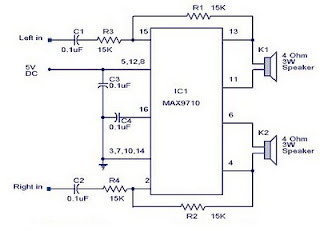

 BTL load with less than 1% THD+N from a 7VDC power supply.
 High Voltage 3 Watt Audio Power Amplifier Circuit Diagram