Wednesday, December 18, 2013

Digital Remote Thermometer

Remote sensor sends data via mains supply, Temperature range: 00.0 to 99.9 °C

This circuit is intended for precision centigrade temperature measurement, with a transmitter section converting to frequency the sensors output voltage, which is proportional to the measured temperature. The output frequency bursts are conveyed into the mains supply cables. The receiver section counts the bursts coming from mains supply and shows the counting on three 7-segment LED displays. The least significant digit displays tenths of degree and then a 00.0 to 99.9 °C range is obtained. Transmitter-receiver distance can reach hundred meters, provided both units are connected to the mains supply within the control of the same light-meter.

Transmitter circuit operation:

IC1 is a precision centigrade temperature sensor with a linear output of 10mV/°C driving IC2, a voltage-frequency converter. At its output pin (3), an input of 10mV is converted to 100Hz frequency pulses. Thus, for example, a temperature of 20°C is converted by IC1 to 200mV and then by IC2 to 2KHz. Q1 is the driver of the power output transistor Q2, coupled to the mains supply by L1 and C7, C8.

Transmitter Circuit diagram :

digital_remote_thermometer_reciever_schematic_circuit diagram 

Transmitter Parts :

R1 = 100K 1/4W Resistors
R2 = 47R 1/4W Resistor
R3 = 100K 1/4W Resistors
R4 = 5K 1/2W Trimmer Cermet
R5 = 12K 1/4W Resistor
R6 = 10K 1/4W Resistor
R7 = 6K8 1/4W Resistor
R8 = 1K 1/4W Resistors
R9 = 1K 1/4W Resistors
C1 = 220nF 63V Polyester Capacitor
C2 = 10nF 63V Polyester Capacitor
C3 = 1µF 63V Polyester Capacitor
C4 = 1nF 63V Polyester Capacitors
C5 = 2n2 63V Polyester Capacitor
C6 = 1nF 63V Polyester Capacitors
C7 = 47nF 400V Polyester Capacitors
C8 = 47nF 400V Polyester Capacitors
C9 = 1000µF 25V Electrolytic Capacitor
D1 = 1N4148 75V 150mA Diode
D2 = 1N4002 100V 1A Diodes
D3 = 1N4002 100V 1A Diodes
D4 = 5mm. Red LED
IC1 = LM35 Linear temperature sensor IC
IC2 = LM331 Voltage-frequency converter IC
IC3 = 78L06 6V 100mA Voltage regulator IC
Q1 = BC238 25V 100mA NPN Transistor
Q2 = BD139 80V 1.5A NPN Transistor
T1 = 220V Primary, 12+12V Secondary 3VA Mains transformer
PL = Male Mains plug & cable
L1 = Primary (Connected to Q2 Collector): 100 turns
Secondary: 10 turns
Wire diameter: O.2mm. enameled
Plastic former with ferrite core. Outer diameter: 4mm.

Receiver circuit operation :

The frequency pulses coming from mains supply and safely insulated by C1, C2 & L1 are amplified by Q1; diodes D1 and D2 limiting peaks at its input. Pulses are filtered by C5, squared by IC1B, divided by 10 in IC2B and sent for the final count to the clock input of IC5. IC4 is the time-base generator: it provides reset pulses for IC1B and IC5 and enables latches and gate-time of IC5 at 1Hz frequency. It is driven by a 5Hz square wave obtained from 50Hz mains frequency picked-up from T1 secondary, squared by IC1C and divided by 10 in IC2A. IC5 drives the displays cathodes via Q2, Q3 & Q4 at a multiplexing rate frequency fixed by C7. It drives also the 3 displays paralleled anodes via the BCD-to-7 segment decoder IC6. Summing up, input pulses from mains supply at, say, 2KHz frequency, are divided by 10 and displayed as 20.0°C. 

Receiver Circuit diagram :

digital_remote_thermometer_transmitter_schematic circuit_diagram

Receiver Parts :

R1 = 100K 1/4W Resistor
R2 = 1K 1/4W Resistor
R3 = 12K 1/4W Resistors
R4 = 12K 1/4W Resistors
R5 = 47K 1/4W Resistor
R6 = 12K 1/4W Resistors
R8 = 12K 1/4W Resistors
R9-R15=470R 1/4W Resistors
R16 = 680R 1/4W Resistor
C1 = 47nF 400V Polyester Capacitors
C2 = 47nF 400V Polyester Capacitors
C3 = 1nF 63V Polyester Capacitors
C4 = 10nF 63V Polyester Capacitor
C7 = 1nF 63V Polyester Capacitors
C5 = 220nF 63V Polyester Capacitors
C6 = 220nF 63V Polyester Capacitors
C8 = 1000µF 25V Electrolytic Capacitor
C9 = 100pF 63V Ceramic Capacitor
C10 = 220nF 63V Polyester Capacitors
D1 = 1N4148 75V 150mA Diodes
D2 = 1N4148 75V 150mA Diodes
D3 = 1N4002 100V 1A Diodes
D4 = 1N4002 100V 1A Diodes
D5 = 1N4148 75V 150mA Diodes
D6 = Common-cathode 7-segment LED mini-displays
D7 = Common-cathode 7-segment LED mini-displays
D8 = Common-cathode 7-segment LED mini-displays
IC1 = 4093 Quad 2 input Schmitt NAND Gate IC
IC2 = 4518 Dual BCD Up-Counter IC
IC3 = 78L12 12V 100mA Voltage regulator IC
IC4 = 4017 Decade Counter with 10 decoded outputs IC
IC5 = 4553 Three-digit BCD Counter IC
IC6 = 4511 BCD-to-7-Segment Latch/Decoder/Driver IC
Q1 = BC239C 25V 100mA NPN Transistor
Q2 = BC327 45V 800mA PNP Transistors
Q3 = BC327 45V 800mA PNP Transistors
Q4 = BC327 45V 800mA PNP Transistors
PL = Male Mains plug & cable
T1 = 220V Primary, 12+12V Secondary 3VA Mains transformer
L1 = Primary (Connected to C1 & C2): 10 turns
Secondary: 100 turns
Wire diameter: O.2mm. enameled
Plastic former with ferrite core. Outer diameter: 4mm.

Notes:
  • D6 is the Most Significant Digit and D8 is the Least Significant Digit.
  • R16 is connected to the Dot anode of D7 to illuminate permanently the decimal point.
  • Set the ferrite cores of both inductors for maximum output (best measured with an oscilloscope, but not critical).
  • Set trimmer R4 in the transmitter to obtain a frequency of 5KHz at pin 3 of IC2 with an input of 0.5Vcc at pin 7 (a digital frequency meter is required).
  • More simple setup: place a thermometer close to IC1 sensor, then set R4 to obtain the same reading of the thermometer in the receivers display.
  • Keep the sensor (IC1) well away from heating sources (e.g. Mains Transformer T1).
  • Linearity is very good.
  • Warning! Both circuits are connected to 230Vac mains, then some parts in the circuit boards are subjected to lethal potential! Avoid touching the circuits when plugged and enclose them in plastic boxes.
Source :  http://www.ecircuitslab.com/2011/05/digital-remote-thermometer.html
Read More..

Tuesday, December 17, 2013

Sound Activated Switch II

With this sound activated switch, control by sound may be very useful, not just on a robot but also for a bit of home automation, for example a sound-activated light responding to a knock on the door or a hand clap. The light will be automatically switched off after a few seconds. An alternative use is burglar protection - if someone wants to open the door or break something the light will come on, suggesting that someone’s at home. The circuit can work from any 5–12 VDC regulated power supply provided a relay with the suitable coil voltage is used.

Sound activated switch circuit diagram

Circuit Project: Sound Activated Switch circuit

When you first connect the supply voltage to the sound activated switch circuit, the relay will be energized because of the effect of capacitor C2. Allow a few seconds for the relay to be switched off. You can increase or decrease the ‘on’ period by changing the value of C2. A higher value results in a longer ‘on’ period, and vice versa. Do not use a value greater than 47μF.

Biasing resistor R1 determines to a large extent the microphone sensitivity. An electret microphone usually has one internal FET inside which requires a bias voltage to operate. The optimum bias level for response to sound has to be found by trial and error. All relevant electrical safety precautions should be observed when connecting mains powered loads to the relay contacts.
Read More..

Electronic 7 Digit Combination Lock

This 7-digit combination lock can be easily hard-wired for any combination that you choose. The circuit uses a 4-bit, divide-by-8 Johnson counter (IC1), ten push button switches and NPN transistor T1. At power-‘on,’ capacitor C2 connected to pin 15 of IC1 charges to high level through 820-kilo-ohm resistor, holding the counter in the reset state.

 In this condition, output O0 (pin 2) of counter IC1 is high, while all other outputs are low. When switch S2 is pressed, transistor T1 conducts and capacitor C2 discharges via diode D1 and resistor R2, releasing the counter’s reset input. When S2 is released, T1 cuts off and its collector is pulled high, generating a rising edge on the counter’s input clock pin 14.

 Electronic Combination Lock Circuit Diagram
 Electronic Combination Lock Circuit Diagram
Capacitor C1 and resistor R3 in the base circuit of transistor T1 form a simple filter to prevent switch contact bounce from generating multiple clock pulses on pin 14 of IC1. The clock pulse advances IC1’s count by one, so O0 goes low and O1 goes high. Therefore press switch S7 next, as it’s wired to output O1.

The time required for capacitor C1 to charge to logic high level is the maximum time that can lapse between switches pressed. Otherwise, the counter will reset. When all switches have been pressed in the correct sequence (S2-S7-S3-S4-S5-S2-S2 as shown), output O7 (pin 10) of the counter goes high for about ten seconds. This output is fed to driver transistor T2 to drive the solenoid valve and open the lock.

Assemble the circuit on a common PCB and enclose in a plastic cabinet. Connect the solenoid valve to the circuit using a flexible wire. While soldering, take care to avoid shortings. Use IC base for ease of troubleshooting. Connect the switches for opening the lock at the top of the plastic case.
Read More..

Black Light

This circuit is a simple ultra violate light that can be powered by a 6 volt battery or power supply that is capable of supplying 1 or more amps.


Parts:

C1 0.0047uf Mono Capacitor
C2 0.1uf Disc Capacitor
D1, D2 1N4007 Diode
FTB Filtered Blacklight Tube
IC1 555 Timer IC
P1 10k Trim Pot
Q1 TIP30 PNP Power Transistor
R1 470 Ohm Resistor
R2 270 Ohm Resistor
T1 Medium Yellow Inverter Transformer
MISC IC Socket, Heat Sink For Q1, Screw, Nut, Wire and PC Board

Notes:

1. P1 changes brightness of the black light tube.

Source: http://www.diy-electronic-projects.com/p144-Black-Light
Read More..

The customer does not need to use cell phone jammer

The customer does not need to use cell phone jammer
In-depth development of high-tech industry clusters and innovation clusters to guide and role model, so that the industrial base to the development of high-tech industries in Xiamen "leading pack". Further play to the National Torch Plan-driven and demonstration of high-tech industries, mining Xiamen potential for industrial development, the declaration of Xiamen optoelectronic and electrical characteristics of industrial base, and foster new economic growth point, strengthen the science and technology to sustainable economic and social coordination to support the development and a leading role. With the development of mobile phones in the field of peoples lives began to play an increasingly irreplaceable role.Students through the card to achieve the schools internal consumption, school deployed a swipe card reader to read the information of the student card, automatic debit through the back office software, the system automatically sends the student consumer details and account balance information. The content of the message including student name, the amount of consumption, consumer locations, consumption patterns, time, balance. Account recharge transfers to remind. Card user account recharge or transfer the card system can be set up SMS alerts to remind users to recharge or transfer of relevant information. Includes student name, the amount of time, recharge the way, whether successful. The cell phone jammer system can change the background radio power value to the level value.
School subsidy payment reminder. The school issue related to grants, the system sends SMS alerts when deposited in the campus card accounts. Includes student name, the amount of time. The balance of early warning alerts. The system can be set for each card balance early warning function, when consumption is close to a predetermined amount, the system will automatically trigger the early warning mechanism, tell cardholders balance is running low, please recharge to avoid affecting the use, use the SMS method. Upstream business: that initiated by the user message, "One Card" system reply message. The campus card loss (UL). User campus card is lost, report the loss of command messages sent via cell phone to report the loss to the campus card system.Engel coefficient of rural residents dropped from 49.4% last year to 46.6%. This shows that regardless of urban residents or rural residents have consumer demand for mobile phone industry. With Jingzhou sustained economic development, it also has other aspects of consumption. This helps the mobile phone industry to expand and to explore the potential of Jingzhou consumption on the market of Jingzhou.
Read More..

How to Build a Simple Power supply Circuit Diagram

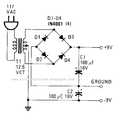
To day i share this post how to Build a simple power-supply circuit diagram lets start . This simple power supply circuit diagram delivers plus and minus 9 V to replace two 9-V batteries. The rectifier circuit is actually two separate full-wave rectifiers fed from the secondary of the transformer. One full-wave rectifier is composed of diodes D1 and D2, which develop +9 V, and the other is composed of D3 and D4, which develop -9 V. 

Each .diode from every pair rectifies 6.3 Vac, half the secondary voltage, and charges the associated filter capacitor to the peak value of the ac waveform, 6.3 x 1.414 ~ 8.9 V. Each diode should have a PIV, Peak Inverse `Voltage, rating that is at least twice the peak voltage from the transformer, 2 x 8.9 ~ 18 V. The 1N4001 has a PIV of 50 V. I hope you are enjoy this circuit.

Simple Power supply Circuit Diagram

Simple Power supply Circuit Diagram


Read More..

Monday, December 16, 2013

Building A Park Aid

This circuit was designed as an aid in parking the car near the garage wall when backing up. LED D7 illuminates when bumper-wall distance is about 20 cm., D7+D6 illuminate at about 10 cm. and D7+D6+D5 at about 6 cm. In this manner you are alerted when approaching too close to the wall. All distances mentioned before can vary, depending on infra-red transmitting and receiving LEDs used and are mostly affected by the color of the reflecting surface. Black surfaces lower greatly the devices sensitivity.

Building A Park Aid Ciruit
Park Aid Circuit Diagram

Obviously, you can use this circuit in other applications like liquids level detection, proximity devices etc. IC1 forms an oscillator driving the infra-red LED by means of 0.8mSec. pulses at 120Hz frequency and about 300mA peak current. D1 & D2 are placed facing the car on the same line, a couple of centimeters apart, on a short breadboard strip fastened to the wall. D2 picks-up the infra-red beam generated by D1 and reflected by the surface placed in front of it.

The signal is amplified by IC2A and peak detected by D4 & C4. Diode D3, with R5 & R6, compensate for the forward diode drop of D4. A DC voltage proportional to the distance of the reflecting object and D1 & D2 feeds the inverting inputs of three voltage comparators. These comparators switch on and off the LEDs, referring to voltages at their non-inverting inputs set by the voltage divider resistor chain R7-R10.

Notes:


  1. Power supply must be regulated (hence the use of IC3) for precise reference voltages. The circuit can be fed by a commercial wall plug-in power supply, having a DC output voltage in the range 12-24V.
  2. Current drawing: LEDs off 40mA; all LEDs on 60mA @ 12V DC supply.
  3. The infra-red Photo Diode D2, should be of the type incorporating an optical sunlight filter: these components appear in black plastic cases. Some of them resemble TO92 transistors: in this case, please note that the sensitive surface is the curved, not the flat one.
  4. Avoid sun or artificial light hitting directly D1 & D2.
  5. If your car has black bumpers, you can line-up the infra-red diodes with the (mostly white) license or number plate.
  6. Its wiser to place all the circuitry near the infra-red LEDs in a small box. The 3 signaling LEDs can be placed far from the main box at an height making them well visible by the car driver.
  7. The best setup is obtained bringing D2 nearer to D1 (without a reflecting object) until D5 illuminates; then moving it a bit until D5 is clearly off. Usually D1-D2 optimum distance lies in the range 1.5-3 cm.
  8. If you are needing a simpler circuit of this kind driving a LED or a relay, click Infra-red Level Detector
Read More..