Showing posts with label inverter. Show all posts

Tuesday, September 3, 2013

500W Mos Fet Power Inverter from 12V to 110V 220V

Inverter Circuit Diagrams

This circuit will provide a very stable "Square Wave" Output Voltage. Frequency of operation is determined by a pot and is normally set to 60 Hz. Various "off the shelf" transformers can be used. Or Custom wind your own FOR BEST RESULTS. Additional MosFets can be paralleled for higher power. It is recommended to Have a "Fuse" in the Power Line and to always have a "Load connected", while power is being applied. The Fuse should be rated at 32 volts and should be approximately 10 Amps per 100 watts of output. The Power leads must be heavy enough wire to handle this High Current Draw!

Inverter Circuit Diagrams

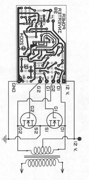
Appropriate Heat Sinks Should be used on the RFP50N06 Fets. These Fets are rated at 50 Amps and 60 Volts. ** Other types of Mosfets can be substituted if you wish. The LT1013 offers better drive that the LM358, but its your choice. The Power transformer must be capable of handling the chosen wattage output. Also, Appropriate Heat Sinks are Necessary on the Mos-Fets. Using a rebuilt Microwave transformer as shown below, it should handle about 500 watts Maximum. It requires about 18 turn Center-Tapped on the primary. To handle 500 watts would require using a 5 AWG wire. Pretty Heavy Stuff, but so is the current draw at that power.

Inverter Circuit Diagrams
Read More..

Saturday, August 3, 2013

Panasonic Microwave Oven Inverter HV Power Supply

Nearly all Panasonic microwave ovens now use an Inverter, and are always labelled with “Inverter” on
the front.

The High Voltage Power Supply Unit (HV PSU)
The HV PSU measures 165mm x 105mm x 60mm and weighs 650g.
 At left is the control daughter board. In front of that on the main board are the opto-isolators for the control and status signals brought out to the green connector. Back left is the rectified mains filter choke. The mains rectifier and switching transistors can just be seen on the heatsink behind the transformer. The mains filter capacitor is at right rear. The HV rectifiers and filters (doubler) are right front – white wires are the HV output from the transformer. The green wire is for grounding the HV +ve. The two lugs t right are for connecting HV -ve and heater to the magnetron. The winding thatcan be seen on the transformer is the primary and is made from 3mm finely stranded wire.

Here’s a view of the control end: 


This is the high voltage end:


The circuit for the HV PSU is below 

Notes about the circuit:
1. Apart from the block diagram, there is no information on the Inverter cont(o)rol circuit. The circuit itself is centred on one large, unmarked IC, so no help there.
2. The control and status signals seem to be a digital stream (2-3v suggestsa 5V data stream). They are opto-isolated because the majority of the circuit is at mains potential  (**BEWARE**). The part that isn’t is at 4kV (*** REALLY BEWARE ***)
3. The mains input side is monitored for both current and (under) voltage. No indication of what the control circuit does with this information.
4. The mains filter capacitor (C702) is very small – only 4uF. In a “normal” switching supply, there is usually 220 or 470 uF in this position.
5. Q701 that does all the hard work is a very heavy duty IGBT – a GT60N90 - 900V @ 60 A. Q702 forms some sort of flywheel circuit. This circuit from a Toshiba IGBT application note looks similar:
6. The HV side has a full-wave doubler rectifier and is marked 4kV @  300mA. Unlike the classic microwave oven transformers (where one side of the winding is grounded), this means that the secondary must be well insulated from ground on both sides. A simple reconfiguration of the rectifier (replace the caps with diodes) into a bridge circuit should yield 2kV @ 600mA (depending on the diode ratings)
7. The HV filter capacitors are only 8200 pF each, effectively giving 4100pF in the doubler. Considering that the inverter runs at about 30kHz, the reactance is equivalent to that  of a 5uF capacitor at 50Hz.
8. The positive side of the HV is grounded, so it’s a –4kV supply. Don’t simply swap the ground from the positive to the negative to get a +4kV supply, as the core of the transformer is also connected to this ground trace and will suddenly rise to 4kV above ground with disastrous and potentially fatal results. Instead, reverse the polarity of the rectifier diodes to get +4kV.
Read More..

Tuesday, July 30, 2013

12VDC – 220VAC Inverter Using Cmos CD4047

12VDC – 220VAC Inverter Using Cmos CD4047
This circuit inverter converts 12V DC battery to AC 22oV as the replacement of home energy. The inverter can be used for small electronic devices such as lamps, radio, phone charger, disc player, etc.
12VDC – 220VAC Inverter Using Cmos CD4047
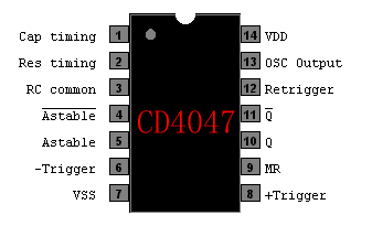
The inverter circuit is a central component, the CMOS 4047, and converts a DC voltage of 12 V to 220 V AC voltage. 4047 is used as an astable multivibrator. The pin 10 and 11 we find a symmetrical rectangular signal is amplified by Darlington transistors T1 and T2 trailer, and finally reaches the secondary coil of a transformer of the network (2 x 10V/100VA). Primary coil voltage is 220 AC voltage terminals. For best performance, use a toroidal core transformer with low losses. P1 to the output frequency can be regulated within certain limits (50 ... 400 Hz).
Read More..

Friday, July 5, 2013

500W Mos Fet Power Inverter from 12V to 110V 220V

Inverter Circuit Diagrams

This circuit will provide a very stable "Square Wave" Output Voltage. Frequency of operation is determined by a pot and is normally set to 60 Hz. Various "off the shelf" transformers can be used. Or Custom wind your own FOR BEST RESULTS. Additional MosFets can be paralleled for higher power. It is recommended to Have a "Fuse" in the Power Line and to always have a "Load connected", while power is being applied. The Fuse should be rated at 32 volts and should be approximately 10 Amps per 100 watts of output. The Power leads must be heavy enough wire to handle this High Current Draw!

Inverter Circuit Diagrams

Appropriate Heat Sinks Should be used on the RFP50N06 Fets. These Fets are rated at 50 Amps and 60 Volts. ** Other types of Mosfets can be substituted if you wish. The LT1013 offers better drive that the LM358, but its your choice. The Power transformer must be capable of handling the chosen wattage output. Also, Appropriate Heat Sinks are Necessary on the Mos-Fets. Using a rebuilt Microwave transformer as shown below, it should handle about 500 watts Maximum. It requires about 18 turn Center-Tapped on the primary. To handle 500 watts would require using a 5 AWG wire. Pretty Heavy Stuff, but so is the current draw at that power.

Inverter Circuit Diagrams
Read More..

Thursday, April 4, 2013

Voltage Inverter Using Switch Mode Regulator

This circuit uses a step-up switch-mode regulator, which is usually used to produce a positive supply, to generate a regulated negative output voltage. The device used here is the MIC4680 from Micrel (www.micrel.com), but the idea would of course work with similar regulators from other manufacturers. Because of coil L1, which performs the voltage conversion by the intermediate storage of energy in the form of a magnetic field, the output is effectively isolated from the input. We can therefore connect the right-hand side of L1 to ground rather than to the positive output without causing a large current to flow. Then we connect the ground pin of the regulator IC and all the components connected to it as the negative voltage output, isolated from ground.

Voltage Inverter Using Switch-Mode Regulator

The components on the output side of the regulator are connected as usual: flywheel diode D1, coil L1 and the voltage divider formed by R1 and R2. These last two components set the output voltage, according to a formula given in the data sheet. Example component values for the MIC4680 used here are given in the table. The input voltage should lie within the permitted range for the regulator used, and must in any case be at least as great in magnitude as the desired output voltage (here +5 V or +12 V), so that the step-down regulation technique can wor.

Voltage Inverter Using Switch-Mode Regulator Table It is important to take care when building this circuit to mount the regulator using an insulator, since generally the GND pin of the device is connected to the heatsink tab. Also, the ON/OFF control input cannot be driven using a normal logic signal, since the regulator’s ground reference is the output voltage rather than ground itself. If the ON/OFF function is required, a level shifter or optocoupler must be used.

Copyright : www.elektor.com

Read More..