Saturday, August 31, 2013

Simple Operational Amplifier DC Motor Driver

Using a simple operational amplifier and some other common electronic components can be designed a very simple DC motor driver that can be used for a 200mA motor application . Rb sets the bias point for transistors Q1 and Q2.

Because Vbe(ON) varies greatly with temperature, a guardband is required to prevent Q1 and Q2 from conducting simultaneously. RB should be selected such that the transistors do not conduct until lM equals the op amp quiescent supply current, Isy . The transistors will begin to conduct at about Vbe (on) = 0.5V. In this project :
RB= [vbe(on)/(lSY+ Im)]= 0.5/(0.0025 + 0.0025)=100 ohms

To maximize voltage swing across the motor, V1 must be minimized. If at full load V1 = 0.2V with V+ = 15V and VBE1 = 0.8V, the voltage across the motor will be:
VM = (V+ - 2) - VBE1 - V1 = (15 - 2) - 0.8 - 0.2 = 12.0V Vin may be scaled with a resistive divider as:
VIN= (R1 + R2)/R2 With R1 = 240k and R2 = 10k, VIN =5 volt lM = 200mA.
Read More..

Smoke Detector Alarm Using RE46C140

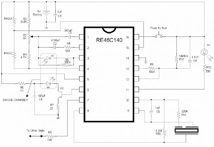
Using the RE46C140 circuit can be designed a very simple smoke detector alarm using few external electronic components . The RE46C140 IC is a low power CMOS photoelectric type smoke detector IC that will provide all the required features for a photoelectric type smoke detector project . This smoke detector alarm design incorporates a gain selectable photo amplifier for use with an infrared emitter detector pair. An internal oscillator strobes power to the smoke detection circuitry for 100us every 10 seconds to keep standby current to a minimum. If smoke is sensed the detection rate is increased to verify an alarm condition.

Smoke Detector Alarm Circuit Diagram


An interconnect pin allows multiple detectors to be connected such that when one units alarms, all units will sound. In standby the LED is pulsed on for 10mS every 43 seconds . In a local alarm condition or the push to test alarm the LED pulse frequency is increased to once every 5 seconds. In the case of a remote alarm the LED not active. In the timer mode of operation the LED is pulsed on for 10mS every 10 seconds.

A comparator compares the photo amp output to an internal reference voltage. If the required number of consecutive smoke conditions is met the device will go into local alarm and the horn will be active. The bidirectional IO pin allows interconnection of multiple detectors. In a local alarm condition this pin is driven high immediately through a constant current source. Shorting this output to ground will not cause excessive current. The IO is ignored as an input during a local alarm. This smoke detector circuit must be powered from a 9 volt DC power supply .
Read More..

ULN2004 Water Level Indicator

This ULN2004 electronic project circuit diagram design is a very simple water level indicator circuit project . This ULN2004 water level indicator circuit is very simple and require few external electronic parts .

ULN2004 is a high voltage, high current darlington arrays that contain seven open collector darlington pairs with common emitters . Each channel rated at 500mA and can withstand peak currents of 600mA.

 ULN2004 Water Level Indicator Circuit Diagram

As the water level rise in the tank , it comes in contact with probes P1 through P7 and thereby makes pins 7 trough 1 high sequentially . The corresponding output pins 10 trough 16 go low one after other and LED1 through LED7 will light up . When water comes in contact with the last probe P7 , the buzzer connected to the last pin 16 will sound .

This electronic circuit project must be powered from a fixed output DC voltage that will provide an output voltage between 9 and 12 volts .
Read More..

TDA7275A DC Speed Controller

Using the TDA7275A linear integrated circuit manufactured in a minidip plastic package can be designed a very simple speed regulator electronic project that can be used for speed regulation of small DC motors .


TDA7275A DC Speed Controller Schematic


TDA7275A DC speed controller project is intended for use as speed regulator for DC motors of record players, tape and cassette recorders. This DC motor speed controller circuit project can provide a maximum output current of 1.5 amperes .

This circuit can be powered with a voltage range between 8 and 18 volts . V2 is typically 1.5 volt for Motor ”Run” (Acc. Following data or open) and 1 volt for Motor ”Stop” (Acc. Following data or grounded) .
Read More..

High Power Alarm Driver

In this circuit, a low-powered SCR is used to trigger a higher powered SCR. When a switch is opening (S2, S3, S4) or closing (S5, S6, S7), either SCR1 or SCR2 triggers. This triggers SCR3 via D1, D2, and R5. BZ1 is a high-powered alarm of the noninterrupting type. 

High-Power Alarm Driver Circuit Diagram


Read More..

Friday, August 30, 2013

Twin T RC Notch Filter

The two T-notch filter can be used to block unwanted frequencies or if placed in an op amp as a bandpass filter. the notch frequency occurs where the capacitive reactance equals the resistance (Xc = R) and if the values are close, the attenuation can be very high and the notch frequency virtually eliminated,Insertion of the filter depends on the load, the output is connected to the subject so that the resistors must be of much lower value than the load for minimal loss.

Twin-T RC Notch Filter Circuit diagram

For audio frequencies, the filter may act as a bass and treble boost circuit by attenuating the midrange. With 1.5K resistors and capacitors 0.1 uF, the band is in stop-10dB 500 Hz to 2 kHz. The depth and breadth of the reaction can be slightly adjusted to a value of 0.5 R and adding some resistance at the C-values,If the circuit is an operational amplifier is used as a bandpass filter, the response should be reduced to avoid oscillation.
Read More..

Friday, August 16, 2013

Diode less Rectifier Circuit Diagram

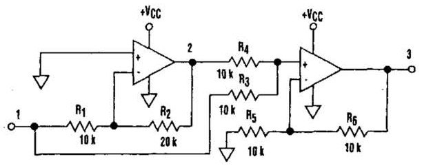
Diode less Rectifier Circuit Diagram . It`s common knowledge that when working with single-supply op amps, implementing simple functions in a bipolar signal environment can be difficult. Sometimes additional op amps and other electronic components are required. Taking that into consideration, can any advantage be attained from this mode The answer lies in this simple circuit (A). Requiring no diodes, the circuit is a high-precision full-wave rectifier with a liigli-frequency limitation equalling that of the op amps themselves. Look at the circuit`s timing diagram (B) to see the principle of operation. The first amplifier rectifies negative input levels with an inverting gain of 2 and turns positive levels to zero .

The second amp, a noninverting summing amplifier, adds the inverted negative signal from the first amplifier to the original input signal. The net result is the traditional waveform produced by full-wave rectification. In spite of the limitation on the input signal amplitude (it must be less than VCCJZ), this circuit can be useful in a variety of setups.

 Diode less Rectifier Circuit Diagram


Diode less Rectifier Circuit Diagram
Read More..