A symmetrical ±5V power supply is often needed for small, battery-operated operational amplifier projects and analogue circuits. An IC that can easily be used for this purpose is the National Semiconductor LM2685. It contains a switched-capacitor voltage doubler followed by a 5-V regulator. A voltage inverter integrated into the same IC, which also uses the switched-capacitor technique, runs from this output voltage. The external circuitry is limited to two pump capacitors and three electrolytic storage capacitors.
The IC can work with an input voltage between +2.85 V and +6.5 V, which makes it well suited for battery-operated equipment. The input voltage is first applied to a voltage doubler operating at 130 kHz. The external capacitor for this is connected to pins 13 and 14. The output voltage of this doubler is filtered by capacitor C3, which is connected to pin 12. If the input voltage lies between +5.4 and +6.5 V, the voltage doubler switches off and passes the input voltage directly through to the following +5-V low-dropout regulator, which can deliver up to 50mA.
C4 is used as the output filter capacitor. All that is necessary to generate the –5-V output voltage is to invert the +5-V voltage. This is done by a clocked power-MOS circuit that first charges capacitor C2, which is connected between pins 8 and 9, and then reverses its polarity. This chopped voltage must be filtered by C5 at the output. The unregulated –5 V output can supply up to 15 mA. The LM 2865 voltage converter IC also has a chip-enable input (CE) and two control inputs, SDP (shut down positive) and SDN (shut down negative).
If CE is set Low, the entire IC is switched off (shut down), and its current consumption drops to typically 6 µA. The CE input can thus be used to switch the connected circuit on or off, without having to disconnect the battery. The SDP and SDN inputs can be used to switch the VPSW and VNSW outputs, respectively. These two pins are connected to the voltage outputs via two low-resistance CMOS switches. This allows the negative output to be separately switched off, whereby the voltage inverter is also switched off. Switching off with SDP not only opens the output switch but also stops the oscillator.
There is thus no longer any input voltage for the –5 V inverter, so the –5 V output also drops out. The SDP and SDN inputs are set Low (< 0.8 V) for normal operation and High (>2.4 V) for switching off the associated voltage(s). The positive output of the LM 2865 is short-circuit proof. However, a short circuit between the positive and negative outputs must always be avoided. The IC is protected against thermal destruction by an over-temperature monitor. It switches off automatically at a chip temperature of around 150 oC. The full type number of the IC is LM 2685MTC. It comes in a TSSOP14 SMD package. National Semiconductor can be found on the Internet under www.national.com.
Read More..
The IC can work with an input voltage between +2.85 V and +6.5 V, which makes it well suited for battery-operated equipment. The input voltage is first applied to a voltage doubler operating at 130 kHz. The external capacitor for this is connected to pins 13 and 14. The output voltage of this doubler is filtered by capacitor C3, which is connected to pin 12. If the input voltage lies between +5.4 and +6.5 V, the voltage doubler switches off and passes the input voltage directly through to the following +5-V low-dropout regulator, which can deliver up to 50mA.
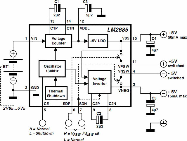 |
| DC 6.5V to ±5V Converter Circuit Diagram |
C4 is used as the output filter capacitor. All that is necessary to generate the –5-V output voltage is to invert the +5-V voltage. This is done by a clocked power-MOS circuit that first charges capacitor C2, which is connected between pins 8 and 9, and then reverses its polarity. This chopped voltage must be filtered by C5 at the output. The unregulated –5 V output can supply up to 15 mA. The LM 2865 voltage converter IC also has a chip-enable input (CE) and two control inputs, SDP (shut down positive) and SDN (shut down negative).
If CE is set Low, the entire IC is switched off (shut down), and its current consumption drops to typically 6 µA. The CE input can thus be used to switch the connected circuit on or off, without having to disconnect the battery. The SDP and SDN inputs can be used to switch the VPSW and VNSW outputs, respectively. These two pins are connected to the voltage outputs via two low-resistance CMOS switches. This allows the negative output to be separately switched off, whereby the voltage inverter is also switched off. Switching off with SDP not only opens the output switch but also stops the oscillator.
There is thus no longer any input voltage for the –5 V inverter, so the –5 V output also drops out. The SDP and SDN inputs are set Low (< 0.8 V) for normal operation and High (>2.4 V) for switching off the associated voltage(s). The positive output of the LM 2865 is short-circuit proof. However, a short circuit between the positive and negative outputs must always be avoided. The IC is protected against thermal destruction by an over-temperature monitor. It switches off automatically at a chip temperature of around 150 oC. The full type number of the IC is LM 2685MTC. It comes in a TSSOP14 SMD package. National Semiconductor can be found on the Internet under www.national.com.


